Hey there, tech enthusiasts! Today, we’re diving deep into the world of flexible printed circuit boards (Flex PCBs). If you’ve ever wondered what it takes to design a Flex PCB, how it differs from standard PCBs, and the intricate details of their stack-up, you’re in for a treat.
Table of Contents
Flex PCB vs. Standard PCB: Unveiling the Unique Design Challenges
So, you want to design a Flex PCB? Fantastic! But be prepared for a twist because, unlike standard PCBs, Flex PCBs don’t follow a one-size-fits-all formula. Whether it’s a two-layer Flex or a complex multi-layered wonder, each Flex PCB can be a unique puzzle.
You see, in the realm of standard PCBs, the process and stack-up generally remain consistent regardless of the layer count. But when it comes to Flex PCBs, the game changes entirely. You can have ten different Flex PCBs, each with distinct requirements and designs.

What sets them apart? Well, it all starts with something called a “stiffener.” This unassuming element plays a crucial role in the Flex PCB world, adding a touch of rigidity where needed. You’ll want to pay special attention to stiffeners, especially when you have connectors or components that require soldering. Without proper support, bending your Flex PCB can lead to broken solder joints—a designer’s worst nightmare.
The Power of Coverlay: A Flexible Alternative to Solder Mask
Now, let’s talk about something that might just blow your mind: “coverlay.” In standard PCBs, we’re accustomed to using solder mask, that familiar green layer. But in the Flex PCB universe, we opt for coverlay. Why, you ask? Because solder mask, when bent, tends to crack like a brittle old leaf.
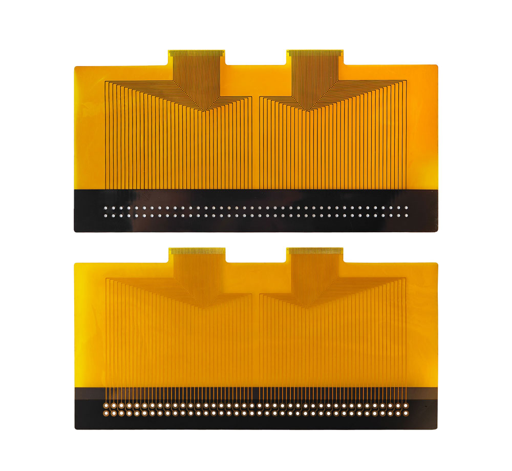
Coverlay, on the other hand, is a game-changer. It’s a flexible film-like material composed of two layers: the capton (you’ll recognize it by its brown color) and adhesive underneath. This dynamic duo ensures your Flex PCB can bend without a hitch. Imagine having a Flex PCB with coverlay on both sides; you can flex it like a pro without fear of damaging critical connections.
But there’s a catch—you can’t create tiny openings in coverlay. So, when you need fine-pitched components or intricate designs, you’ll need to make strategic cuts in the coverlay where your components will reside. Laser machines come to the rescue, allowing precise cuts to accommodate your design needs.
Adhesive: The Glue That Holds It All Together
We’ve talked about stiffeners and coverlay, but now let’s delve into the glue that holds your Flex PCB stack-up together—adhesive. In standard PCB stack-ups, you’ve got pre-pregs serving as the glue-like materials between different core layers. In the Flex PCB realm, it’s not pre-pregs you’re dealing with; it’s something special known as PI or Kapton.
PI stands for polyimide, and it’s one of the go-to materials for adhesive in the Flex PCB world. Picture it as the silent hero, ensuring that the various layers of your Flex PCB adhere seamlessly. This adhesive not only binds the layers but also plays a crucial role in maintaining the board’s flexibility.
When engineers specify Flex PCB stack-ups for particular applications, they carefully consider the adhesive’s characteristics. For instance, if you need a high-speed Flex PCB or require precise impedance control, the choice of adhesive becomes pivotal. So, whether it’s PI or Kapton, these materials are selected with the end application in mind, ensuring your Flex PCB performs flawlessly.

Choosing the Right Stack-Up: It’s All About the Application
Now, here’s a question for you: Do you have a favorite Flex PCB stack-up? Well, it turns out, choosing a favorite isn’t that simple in the world of Flex PCB design. Every Flex PCB is like a unique piece of art, crafted to fit a specific purpose. So, instead of having a one-size-fits-all favorite, designers tend to lean towards materials from trusted manufacturers like Topfast.
Topfast offers a wide range of materials, including FR4 for added rigidity, coverlay for flexibility, and a plethora of polymide options like TK materials. These choices provide the versatility needed to create the perfect stack-up for your Flex PCB based on the application’s requirements.
And here’s the secret sauce—when you dive into these materials’ data sheets, you’ll find a treasure trove of information. They’ll spell out the variations in thickness for capton and adhesive, giving you the power to fine-tune your stack-up like a pro.
Fine-Tuning Your Flex PCB Stack-Up: A Designer’s Toolkit
In our ongoing quest to unlock the mysteries of Flex PCBs, we’ve unveiled some of the fundamental aspects of stack-up design. But as any experienced designer knows, the devil’s in the details. So, let’s explore some of the finer points of creating the perfect Flex PCB stack-up.
Customizing Flex Stack-Up for Your Unique Needs
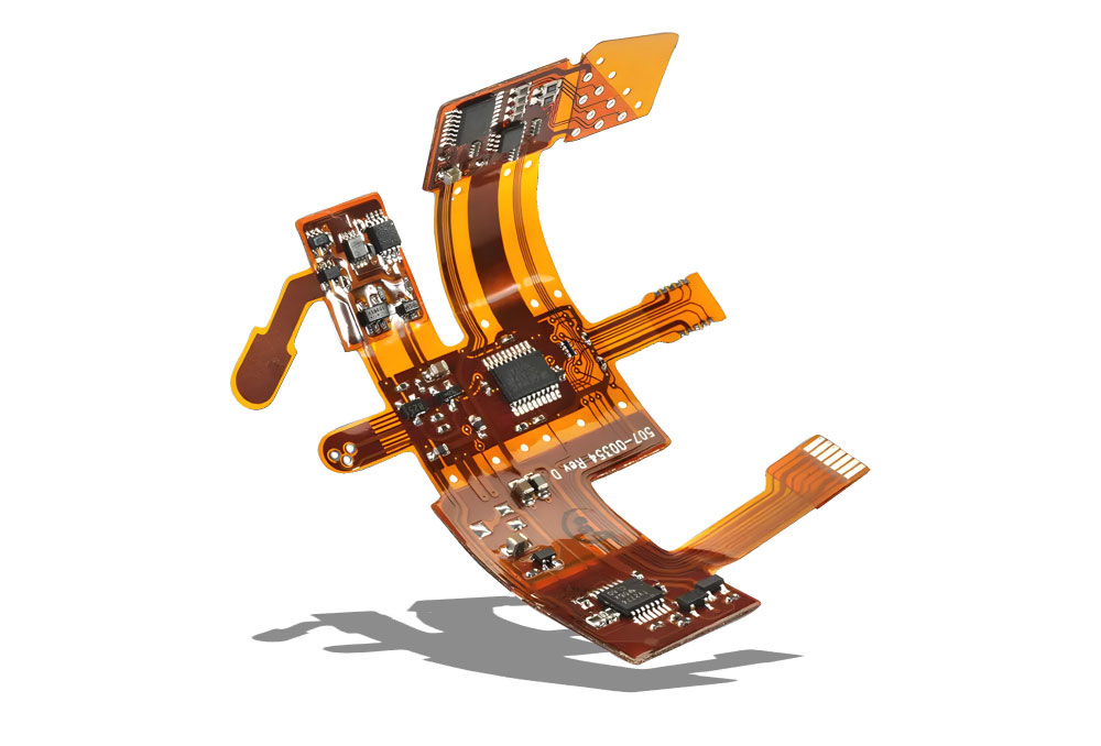
Flex PCBs are all about flexibility, and that means they come in various flavors. You can have pure Flex PCBs, Flex-Rigid hybrids, or even combinations that suit your specific application. The beauty of Flex PCBs lies in their adaptability.
Imagine a Flex PCB with a flexible section for bending and a rigid section for components that need stability. This is where the magic happens! You can seamlessly combine different materials, stiffeners, and adhesives to create the perfect balance between flexibility and rigidity.
For instance, if you’re working on a wearable device, you’d want the Flex PCB to be pliable and comfortable to wear. But if you’re designing a PCB for an automotive application, it should withstand extreme temperatures and vibrations, requiring a different stack-up approach.

Special Considerations for High-Speed and Impedance Control Flex PCBs
Flex PCBs aren’t just for bending—they can also handle high-speed data transmission and precise impedance control. But achieving this requires a keen eye for detail in your stack-up design.
When dealing with high-frequency signals, every millimeter counts. Ensuring signal integrity and minimizing crosstalk is paramount. That’s where controlled impedance comes into play. By carefully selecting materials and their thicknesses, you can achieve the precise impedance values needed for your application.
Heat Dissipation and Component Mounting
Flex PCBs aren’t just about signals; they can also handle components like LEDs and cameras. These components generate heat, which needs to be managed effectively. One way to tackle this is by adding aluminum stiffeners to dissipate heat and maintain the PCB’s structural integrity.
When mounting components on a Flex PCB, consider not only their electrical characteristics but also their mechanical demands. Proper stiffening and support will ensure the longevity and reliability of your design.

Putting It All Together: Your Unique Flex PCB Stack-Up
In the world of Flex PCBs, no two designs are alike. The stack-up you create will be as unique as your application’s requirements. So, remember to:
- Customize: Tailor your Flex PCB stack-up to match your specific needs.
- Consider Application: Think about how and where your Flex PCB will be used and design accordingly.
- Signal Integrity: Pay attention to controlled impedance for high-speed applications.
- Heat Management: Incorporate solutions for heat dissipation when dealing with heat-producing components.
Creating the perfect Flex PCB stack-up is an art as much as it is science. So, embrace the flexibility, adaptability, and endless possibilities that Flex PCBs offer. As you continue your journey in the world of electronics and technology, keep experimenting, innovating, and pushing the boundaries of what’s possible with Flex PCB stack-up design. Until next time, happy designing, and stay curious!