1-30
Layers Supported
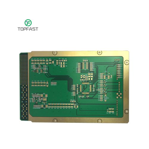
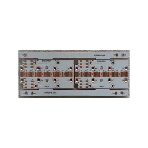
Metal Core PCB
GET A QUOTE
→
Custom Metal PCB Manufacturer & MCPCB Assembly Services
Specialized metal-substrate circuit boards for superior heat dissipation in high-power applications — from prototype to mass production.
Customized Design
1–12 layers, aluminum / copper / hybrid substrates
Fast Turnaround
Prototype delivery in 2–7 days
Quality Assured
ISO 9001 · IATF 16949 · UL certified · full thermal testing
DFM Support
Free Design-for-Manufacturing review before production