Automotive electronics operate in one of the harshest environments in the electronics industry.
Unlike consumer devices, automotive PCBA must withstand:
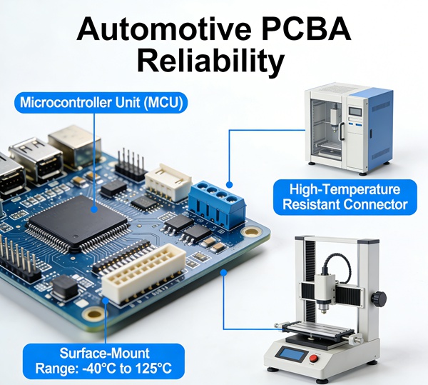
- Wide temperature range (–40°C to +125°C or higher)
- Continuous vibration
- Thermal cycling
- High humidity
- Electrical load transients
- Long service life (10–15 years)
Reliability is not optional—it is a qualification requirement.
This article explains how PCBA design, PCB structure, material selection, and assembly control work together to meet automotive-grade standards.
Table of Contents
Automotive Environment Stress Profile
Typical automotive stress factors include:
1. Thermal Cycling
Engine control units and power modules experience repeated heating and cooling.
Repeated expansion and contraction causes:
- Solder fatigue
- Micro-cracking
- Delamination
- Via barrel cracking
This directly relates to solder joint reliability discussed in: BGA solder joint reliability
2. Vibration and Mechanical Shock
Road vibration introduces cyclic mechanical stress.
Weak solder joints or heavy components without reinforcement can fail prematurely.
Design must consider:
- Component anchoring
- Board thickness
- Mechanical support points
3. High Temperature Operation
Automotive under-hood electronics may operate continuously above 105°C.
Material selection becomes critical:
- High Tg laminate
- Low CTE materials
- Stable dielectric properties
Warp behaviour during reflow also affects long-term fatigue performance: pcb warpage reflow deformation
PCB Design Considerations for Automotive Reliability
Symmetric Stack-Up
Unbalanced copper distribution increases internal stress and deformation.
Symmetric stack-up improves:
- Dimensional stability
- Warpage control
- Thermal cycling durability
Via Structure Optimisation
Through-hole vias in high-stress areas are vulnerable.
Recommendations:
- Use filled vias in BGA areas
- Avoid excessive via-in-pad without proper filling
- Control copper plating thickness
Barrel cracking is common in automotive stress environments.
Controlled Impedance and Power Integrity
Automotive systems often include:
- CAN bus
- High-speed communication
- Power control circuits
Impedance control must remain stable under temperature variation.
Material dielectric constant drift must be considered.
Solder Joint Reliability in Automotive Applications
Solder joint fatigue is the most common failure mode.
Factors influencing reliability:
- Solder alloy selection (SAC305 common)
- Joint geometry
- Component stand-off height
- PCB thickness
- Stencil design
Printing consistency is essential: stencil design optimisation smt yield
Automotive production requires strict SPI monitoring and process control.
Component Qualification Standards
Automotive components must meet AEC-Q standards, such as:
- AEC-Q100 (ICs)
- AEC-Q200 (passive components)
These standards define:
- Thermal cycling tests
- Mechanical stress tests
- Humidity resistance
- Operational life testing
Designing PCBA for automotive use requires matching PCB capability with component qualification.
Conformal Coating and Protection
Automotive PCBA often requires additional protection:
- Conformal coating
- Potting
- Underfill for BGA
- Protective enclosure
Coating improves:
- Moisture resistance
- Corrosion protection
- Vibration tolerance
However, coating must be compatible with repair and inspection processes.
Design for Test (DFT) in Automotive Electronics
Long product lifecycle requires:
- In-circuit test points
- Boundary scan capability
- Functional test coverage
- Failure traceability
Automotive quality systems demand traceability at:
- PCB level
- Component lot level
- Assembly batch level
Reliability includes process documentation, not just design strength.
Failure Modes in Automotive PCBA
Common automotive failures include:
- Solder fatigue cracking
- Via barrel cracking
- Pad cratering
- Delamination
- Corrosion
- Head-in-pillow defects
Most failures are cumulative effects of thermal and mechanical stress over time.
Collaboration Between Fabrication and Assembly
Automotive reliability cannot rely solely on assembly.
Fabrication quality plays a foundational role:
- Lamination quality
- Resin content control
- Copper thickness consistency
- Controlled drilling parameters
See related discussion: pcb manufacturing process
High-reliability PCBA begins at the fabrication stage.
Process Validation for Automotive PCBA
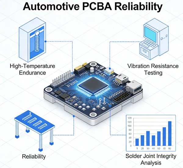
Before mass production, validation testing typically includes:
- Thermal cycling test
- Vibration test
- High temperature storage
- Power cycling test
- Humidity bias test
Qualification testing simulates long-term field conditions.
Frequently Asked Questions (FAQ)
A: Typically –40°C to +125°C, and sometimes higher for power electronics.
A: Standard FR-4 may be insufficient for high-temperature areas. High Tg materials are often required.
A: Repeated vibration causes cyclic stress, accelerating solder fatigue and potential cracking.
A: Often yes. Increased thickness improves mechanical rigidity and reliability.
A: Not always mandatory, but strongly recommended in high-humidity or vibration environments.
Conclusion
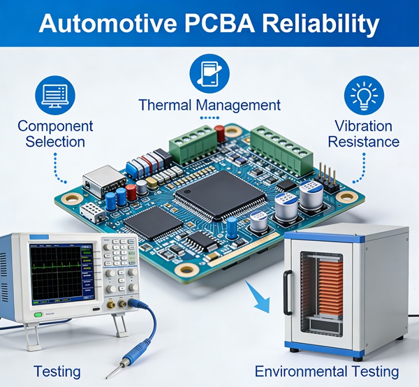
Automotive PCBA reliability is the result of integrated engineering.
Thermal cycling, vibration, material stability, solder joint integrity, and fabrication quality must work together.
Design decisions made at the PCB stage directly impact assembly yield and long-term durability.
Reliable automotive electronics require:
- Balanced stack-up
- Controlled manufacturing process
- Stable assembly parameters
- Thorough validation testing
Automotive-grade reliability is not achieved by a single process improvement—it is built into the entire design and manufacturing system.