Hey there, today, we’re diving into the exciting world of rigid flex design. You might be wondering what it is and why it’s become increasingly popular in recent years. Well, I’ve got some insider knowledge to share with you.
Table of Contents
Rigid Flex: The Game-Changer for Modern Designs
Rigid flex design isn’t just another buzzword; it’s a technology that’s been around for a couple of decades, initially emerging in the military and aerospace industries. Why? To meet their stringent demands for weight, space, and reliability. But here’s the kicker: it’s no longer exclusive to these sectors. Rigid flex is now making its way into the mainstream, and if you’re not using it, you could be missing out on the key to achieving optimal space, weight, and reliability for your designs.
Now, before we get into the nitty-gritty of rigid flex design, let’s talk cost.
Cracking the Cost Code of Rigid Flex Design
Alright, let’s address the elephant in the room: cost. You might have heard that designing with rigid flex can be expensive – and it’s true, but there’s more to the story. When compared to traditional PCB fabrication, rigid flex does come with a higher price tag, possibly double or more. But don’t let that scare you away just yet.
Here’s the deal: You have the power to manage these costs effectively. How? By making smart decisions about layer stack-up and design constraints. Your fabricator can be your ally in this journey, guiding you towards a budget-friendly solution that meets your needs. In the end, you’ll find that the cost of rigid flex falls somewhere in the middle – a reasonable investment considering the incredible benefits it offers.
One Design, Two Worlds: Understanding Rigid Flex Basics
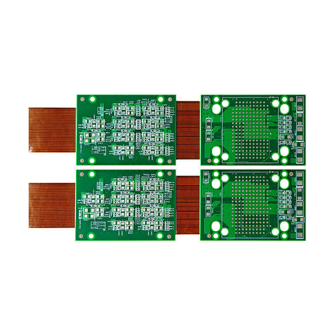
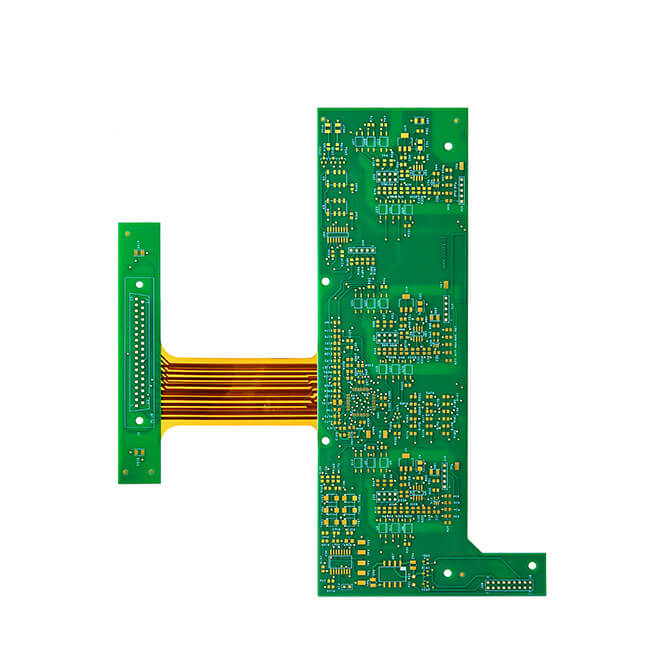
Now that we’ve tackled the cost, let’s dive into the basics of rigid flex design. Picture this: you’re not creating two separate boards—one rigid and one flexible. No, it’s more like designing a single, cohesive unit where the rigid and flexible sections seamlessly coexist.
Think of it as a traditional PCB interconnected by flexible PCB sections. This unified design ensures optimal performance and reliability. But, to pull it off, you need to pay close attention to some critical factors.
Bending Rules: Mastering the Art of Flexibility
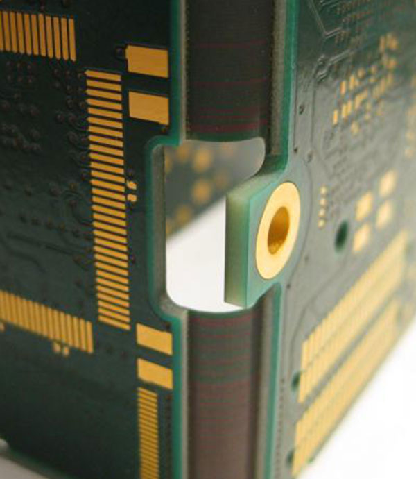
The key to successful rigid flex design lies in understanding the bending points and the bending radius. You want to ensure that the bending radius is about ten times the thickness of the flexible section. This rule of thumb ensures that your design can flex without causing any damage.
But there’s more to it than that. You also need to consider the stack-up – the layer configuration that guides your fabricator in constructing your board. You’ll have one stack-up for the rigid sections and another for the flex sections, with the flex layers overlapping into the rigid sections. Symmetry is your best friend here, especially when it comes to the placement of the flexible section within your design.
Now, let’s dig deeper into the nuts and bolts of creating flexible and robust designs.
Routing for Success: Making the Right Connections
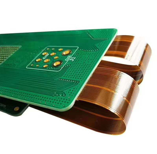
When it comes to routing traces on flexible sections of your PCB, there’s a golden rule: go perpendicular to any bending lines. Why? This ensures that the copper traces won’t fatigue or wear out prematurely as your design flexes and bends. So, always keep this in mind as you plot out your routing strategy.
But that’s not all. When dealing with flexible connectors, ditch the traditional 45 or 90-degree straight traces commonly used on rigid PCBs. In the world of flex, we’re all about curved traces to navigate corners gracefully. This approach prevents copper fatigue and maintains the integrity of your design over time.
Layering It Up: Managing Traces in Two-Layer Flex Sections
In some cases, you’ll have a two-layer flex section in your design. Here’s a critical tip: stagger your traces. This prevents traces from stacking one on top of the other, ensuring that you don’t end up with a thickness build-up where copper layers overlap. The last thing you want is for your design to be compromised due to such structural issues.
Vias: Use Sparingly and Wisely
Vias are essential in PCB design, but in the world of rigid flex, they require a bit of restraint. The flexible material isn’t as stable as the rigid sections, so minimizing the use of vias is a wise move. When you must use them within a flex section, opt for a hole size of no less than 10 and add an additional 10 to the overall diameter. This wider via ensures a robust connection that won’t peel or fatigue during repeated flexing.
Reinforce with Teardrops
Speaking of vias, when you’re routing traces to them, consider using teardrops. These little drops expand the copper area, strengthening the connection to the via. It’s like adding an extra layer of armor to prevent fatigue and potential cracking over time.
Space at the Edge: Vias in the Rigid Section
Now, let’s talk about via placement in the rigid section. Keep them a minimum of 50 mils away from the boundary point of the flex section. Why? This prevents instability and material issues right at the transition point, ensuring that your rigid section remains rock-solid.
Power and Ground: Hatched vs. Solid
Power and ground polygons are critical in any design. In rigid flex, solid polygons won’t cut it because they don’t flex. So, your best bet is to use hatched polygons, which maintain flexibility while providing the conductivity you need. If you must use solid traces, make sure they’re of minimal width and don’t interfere with the bending properties of your design.
These guidelines form the foundation of a successful rigid flex design. Remember, the key to mastering this technology is in the details. It’s all about balancing flexibility with reliability and ensuring that every element of your design contributes to its overall strength.
So, there you have it – the next steps to becoming a rigid flex design pro. In our next installment, we’ll tackle even more advanced techniques and considerations that will set you on the path to creating cutting-edge, space-efficient, and reliable designs.
Now, let’s push the envelope further and delve into some advanced techniques and expert insights.
Taming the Thermal Beast: Heat Management in Rigid Flex
When it comes to thermal management, rigid flex has its own unique challenges. In traditional PCBs, heat dissipation is relatively straightforward, but in rigid flex, you need to be strategic.
Here’s a pro tip: leverage the flexibility of the design by using the flexible sections to dissipate heat more effectively. By positioning heat-generating components strategically on the rigid portions and routing them to the flexible sections, you can take advantage of the natural heat-spreading properties of the flex material. This can be a game-changer for thermal performance in tight spaces.

Shielding and EMI Considerations: Maintaining Signal Integrity
Electromagnetic interference (EMI) is a potential headache for any designer. In rigid flex, it’s no different. To ensure signal integrity and protect against EMI, consider incorporating shielding into your design.
This can be achieved by adding ground layers or even dedicated shielded sections within your rigid flex layout. Just remember that these shielded sections should be electrically connected to your ground plane to provide effective EMI suppression.
Flexible Components and Connectors: A World of Possibilities
Rigid flex designs often involve components and connectors that bridge the gap between rigid and flexible sections. When choosing these components, keep flexibility in mind.
Opt for flexible connectors designed to withstand repeated bending and flexing without compromising performance. These specialized components can be a bit pricier, but they are well worth the investment when it comes to long-term reliability.
Testing and Prototyping: Ensure Success
Before sending your design off for production, don’t forget about testing and prototyping. Given the unique nature of rigid flex, it’s crucial to create physical prototypes to validate the design.
Use 3D animations in your PCB tool to visualize the flex and bend points, or, if possible, create paper or mylar models to fine-tune the mechanics. This hands-on approach can uncover any potential issues and save you headaches down the road.
Collaboration with Fabricators: Your Secret Weapon
Throughout your rigid flex design journey, never underestimate the importance of collaboration with your fabricator. They are your secret weapon to success. Engage with them early in the design process to ensure that your vision aligns with manufacturability.
Your fabricator can provide invaluable insights into material selection, manufacturing techniques, and cost optimization. Their expertise will help you navigate the complex world of rigid flex with confidence.
In conclusion, rigid flex design is not for the faint of heart, but with the right knowledge and a willingness to explore, you can unlock incredible potential for your projects. Remember, it’s a journey of continuous learning and refinement.