Table of Contents
I. Product Overview and Basic Characteristics
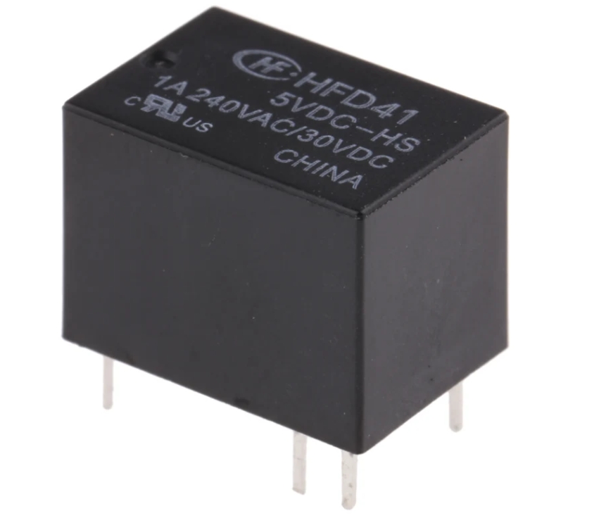
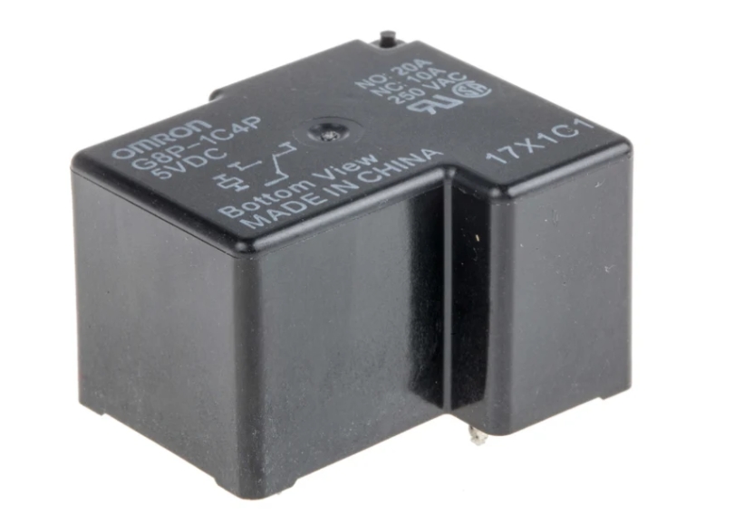
Single-Pole Double-Throw (SPDT) miniature PCB-mounted relays are compact electromechanical switching devices designed for direct mounting on printed circuit boards. These relays feature a movable contact (pole) that switches between two fixed contacts (throws) to achieve circuit conversion control. Due to their compact design and reliable performance, they are widely used in various electronic devices, including automation control systems, household appliances, and safety lighting.
Key Technical Parameters:
- Contact Configuration: 1 Form C (SPDT)
- Size Range: 10×6×5mm to 20×15×10mm
- Coil Voltage: 3VDC to 48VDC / 5VAC to 240VAC
- Load Capacity: 1A to 28A (model dependent)
- Insulation Performance: Up to 5000V dielectric strength between coil and contacts
- Environmental Adaptability: Operating temperature -40℃ to +85℃ (some models up to 125℃)
- Life Expectancy: Mechanical life 100,000 to 1 million operations, electrical life 10,000 to 100,000 operations
II. Product Structure and Operating Principle
1. Mechanical Structure
Miniature SPDT relays feature precision engineering:
- Electromagnetic System: Efficient coil wound with 0.02-0.05mm enameled wire
- Contact System: Composite contacts made of AgNi, AgSnO₂ materials
- Transmission Mechanism: Precision-molded rocker arm structure
- Protective Housing: High-temperature resistant engineering plastics (PA66, PBT)
2. Typical Operation Sequence
- Coil energization creates an electromagnetic field
- The armature is attracted, moving the contact
- Contact switches from NC to NO position
- De-energization returns contact via the reset spring
- Miniature arc chamber quickly extinguishes the arc
III. Market-Leading Product Models
| Brand/Model | Coil Voltage | Contact Rating | Special Features | Application Field |
|---|---|---|---|---|
| TE Connectivity RT315024 | 24VDC | 16A | 10kV surge resistance | Industrial control |
| Panasonic JJM112 | 12VDC | 5A | Automotive grade | Automotive electronics |
| Panasonic CM1-P-24V | 24VDC | 28A | High-current version | Power control |
| Omron G5V-1 | 5VDC | 2A | Ultra-low power | Consumer electronics |
IV. Detailed Key Performance Indicators
1. Electrical Characteristics
- Coil Parameters: 50-200mW power consumption, 3-15ms operate time
- Contact Performance: <100mΩ contact resistance, 1-10ms release time
- Insulation Properties: ≥100MΩ insulation resistance, 500-1500VAC dielectric strength
2. Mechanical & Environmental Characteristics
- Vibration Resistance: 10-55Hz/1.5mm amplitude
- Shock Resistance: 100m/s²
- Safety Certifications: UL/CSA/VDE/CQC/RoHS/REACH
V. Professional PCB Design Guidelines
1. Layout Specifications
- Maintain ≥5mm clearance from heat-generating components
- Avoid placement in high-vibration areas
- Position coil drive circuits near the connectors
2. Wiring Requirements
- Minimum 0.3mm trace width for coil circuits
- ≥1.5mm creepage distance between high-voltage contacts
- Keep sensitive signal lines ≥3mm away from the relay
3. Thermal Optimization
- Use 2oz of copper for high-current models
- Add thermal via arrays
- Implement solder mask openings at critical areas
VI. Application Scenario Analysis
1. Industrial Automation
- PLC output module control
- Safety interlock circuits
- Instrument range switching
2. Consumer Electronics
- Smart home power management
- Portable device charging protection
- Audio signal routing
3. Automotive Electronics
- Body control modules
- EV BMS systems
- On-board charging circuits
4. Communication Equipment
- Base station RF switching
- Network redundancy backup
- Signal test routing
VII. Professional Selection Recommendations
1. Voltage Matching Principles
- Maintain coil voltage within ±10% tolerance
- Contact rating should exceed working voltage by 20%
2. Current Capacity Selection
- Resistive Loads: Match rated current
- Inductive Loads: Allow 2-3x margin
- Capacitive Loads: Implement inrush current suppression
3. Special Environment Adaptation
- High-frequency: Gold-plated contacts
- Humid environments: Sealed models
- High-reliability: Latching relays
VIII. Common Failure Solutions
1. Contact Welding
- Add RC snubber or TVS diode
- Avoid operation at rating limits
- Implement regular maintenance
2. Coil Failure
- Ensure a stable drive voltage
- Add flyback diode protection
- Prevent mechanical stress damage
3. False Operation
- Optimize PCB layout to reduce interference
- Enhance EMI shielding
- Select higher immunity models
IX. Industry Development Trends
- Miniaturization: 01005 package technology in development
- Energy Efficiency: Latching relays achieving μW-level power
- Smart Integration: Built-in status monitoring
- High-Frequency: GHz RF relays under development
- Material Breakthroughs: Graphene-enhanced contacts
With the advancement of IoT and 5G technologies, miniature SPDT PCB relays are evolving toward higher performance and greater intelligence. Proper selection and application of these relays can significantly enhance electronic system reliability and service life, providing dependable circuit control solutions for various electronic devices.