Table of Contents
What is a Metal-Based Printed Circuit Board?
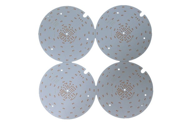
A Metal-Based Printed Circuit Board (Metal Core PCB, abbreviated as MCPCB) is an innovative circuit board solution that uses metal material as the substrate. Compared to traditional FR-4 substrates, MCPCB utilizes its unique metal substrate structure to efficiently transfer heat generated during circuit operation from critical component areas to non-critical areas, such as heat sinks or the metal substrate itself, achieving exceptional thermal management.
Among these, the aluminum substrate provided by TOPFAST is an important category of metal-based printed circuit boards, falling under the technical scope of metal-based copper-clad laminates. This product uses high-quality aluminum material as the core substrate, perfectly combining excellent thermal conductivity with reliable insulation properties. It is particularly suitable for applications with stringent heat dissipation requirements, such as LED lighting and power modules. With advanced production processes and strict quality control, TOPFAST offers high-performance and highly reliable aluminum substrate solutions.
Analysis of Metal Core PCB (MCPCB) Structure
Metal Core Printed Circuit Board (MCPCB), also known as Insulated Metal Substrate (IMS) or Insulated Metal Printed Circuit Board (IMPCB), is designed with efficient heat dissipation as a core principle. Its typical multilayer structure features symmetrical layer distribution. For instance, in a 12-layer board, the metal core is positioned at the center, flanked evenly by six non-metal layers on each side to ensure structural stability and balanced heat transfer.
Core Structural Components
The laminated structure of MCPCB primarily consists of the following key elements:
- Circuit Layer: This is the copper foil layer responsible for electrical connections. To meet high-current transmission requirements, TOPFAST MCPCB utilizes thick copper foil designs, with standard thicknesses ranging from 35 μm to 280 μm, ensuring both current-carrying capacity and reliability.
- Thermal Insulation Layer: This is the core technology of the aluminum substrate. Typically composed of a special polymer filled with ceramic particles, this layer offers excellent thermal conductivity, high electrical insulation strength, and mechanical resilience. TOPFAST employs high-end material systems, such as those similar to IMS-H01 and LED-0601, for this insulation layer. These materials feature minimal thermal resistance, effectively transferring heat and withstanding long-term thermal stress to ensure product longevity.
- Metal Base Layer: Serving as the structural support and primary heat dissipation path, this layer is typically made of highly thermally conductive aluminum or even more conductive copper. TOPFAST’s metal base plates not only provide superior thermal performance but are also suitable for precision mechanical processing like drilling and punching to accommodate complex application requirements.
TOPFAST Aluminum Substrate: Integration of Superior Performance
TOPFAST’s aluminum substrates are representative products in the category of metal-based copper-clad laminates, integrating excellent thermal conductivity, reliable electrical insulation, and outstanding mechanical processability. We strictly adhere to surface treatment standards such as gold plating, immersion gold, tin spraying (including lead-free processes), and OSP anti-oxidation, ensuring that each board maintains high performance and long service life even under demanding conditions.
Types and Advantages of Metal Core PCBs
Metal core printed circuit boards primarily include three types: aluminum-based, copper-based, and iron-based PCBs. The following table provides a detailed comparison of the key characteristics of aluminum-based and copper-based PCBs, along with a systematic summary of the general technical advantages of this category of boards.
| Aspect | Aluminum-Based PCB | Copper-Based PCB |
|---|---|---|
| Core Characteristics | Balanced choice for cost, weight, and performance | Top-tier thermal conductivity and performance for extreme conditions |
| Thermal Conductivity | 5 – 2.0 W/(m·K) | Up to 386 W/(m·K) |
| Coefficient of Thermal Expansion | Approx. 25 μm/m°C | Approx. 17 μm/m°C |
| Typical Substrate Thickness | 2 – 8 mm | Customized based on design requirements |
| Peel Strength | > 9 lb/in | > 9 lb/in |
| Breakdown Voltage | > 3000 V | > 3000 V |
| Flame Resistance Rating | UL 94V-0 | UL 94V-0 |
| Key Advantages | • Excellent thermal conductivity and dissipation • Relatively lightweight • TOPFAST Recommendation: Cost-effective choice | • Superior thermal performance • Better thermal stability • TOPFAST Solution: Designed for high-performance needs |
| Common Types | Single-layer, double-layer, multi-layer aluminum PCBs | Sintered, embedded copper, cold plates, etc. |
Comprehensive Technical Advantages of Metal Core PCBs
| Advantage | Description | Value to Customers |
|---|---|---|
| Efficient Heat Dissipation | Thermal conductivity (1-7 W/m·K) is 8-9 times that of FR-4, rapidly reducing component operating temperatures. | Increases product power density, extends device lifespan, and enhances long-term reliability. |
| Structural Robustness | The metal core layer provides high mechanical strength, with strong resistance to impact and vibration. | TOPFAST products are particularly suitable for harsh environments such as automotive and industrial applications. |
| Design Flexibility | The metal layer can be etched into custom heat sinks (e.g., TOPFAST’s Integrated Heat Dissipation Structure), simplifying system design. | Saves space and cost associated with external heat dissipation components, enabling more compact product designs. |
| High Reliability | Low coefficient of thermal expansion reduces thermal stress, significantly minimizing solder joint fatigue and component separation risks. | Reduces field failure rates, lowers maintenance costs, and safeguards brand reputation. |
| Eco-Friendly Materials | Metal substrates (aluminum, copper) are recyclable, aligning with green manufacturing trends. | Helps customers comply with environmental regulations and build a green product image. |
Metal Core Printed Circuit Board Process Specifications
I. Lamination Structure Design
- A symmetrical lamination structure is adopted to ensure balanced layer distribution on both sides of the metal layer.
- Maintain symmetrical copper layer distribution to prevent board warping.
- Standard dielectric layer thickness: 0.003–0.006 inches.
II. Special Process Requirements
- Plated Through-Hole Treatment: Metal parts must undergo insulation treatment.
- Drilling Process: Diamond-coated metal cutting saws are used.
- Solder Mask Process: White solder mask ink is preferred for LED boards.
III. Detailed Design Specifications
1. Border Design Specifications
- Maintain a minimum distance of ≥1.5mm between the aluminum board edge and SMD component silkscreen/plug-in hole pin edges.
- Internal and external slot chamfer range: 0.8–1.0mm.
- Open a full slot when the distance between component hole walls is <1.15mm.
- Standard aluminum board thickness: 1.5mm (maximum not exceeding 8mm).
- For thickness >1mm, the narrowest border dimension should be ≥3mm.
- For thickness <1mm, the narrowest border dimension should be ≥5mm.
2. Surface Treatment Options
- Multiple processes available: HASL, ENIG, Gold Plating, etc.
- HASL is not recommended for copper-based boards.
IV. Process Specifications for Various Metal Core PCBs
Single-Sided Metal Core PCB
| Process Type | Drilling Specifications | Special Requirements |
|---|---|---|
| PP Lamination | ① Aspect ratio 10:1 ② Component holes ≥0.8mm ③ Vias 0.3–0.8mm | Counterbore ≥1.0mm Angle 82–165° |
| Dielectric Bonding | ① Hole wall spacing ≥0.5mm ② Component holes ≥0.8mm ③ Vias 0.3–0.8mm | Metal core tolerance ±0.1mm |
Application Scope: LED lighting and other scenarios requiring heat dissipation.
Double-Sided/Multi-layer Metal Core PCB
- Drilling Specifications:
- Aspect ratio 10:1
- Component holes ≥1.0mm
- Vias 0.3–0.8mm
- Board thickness range: 0.8–3.5mm (maximum 8mm)
Application Scope: Communication equipment, electronic control systems.
Sintered Metal Core PCB
- Copper Block Specifications:
- Thickness: 1.0/1.5/2.0/3.0mm
- Area: 50×50mm to 200×200mm
- Design Key Points:
- Connection areas must have exposed copper.
- At least one 0.3mm vent hole per 20×20mm area.
- Solder mask dams to prevent solder flow.
- Surface Process: ENIG (supports 2 reflow cycles).
Application Scope: Heat dissipation solutions for high-power components.
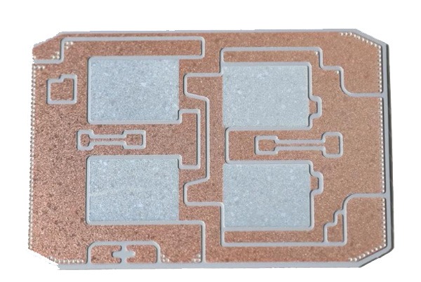
Embedded Copper Metal Core PCB
- Copper Block Requirements:
- Size: 3×3mm to 60×80mm
- Thickness: 1.0–3.0mm
- Spacing: ≥7mm
- Process Limitations:
- 20mil keep-out zone around copper blocks.
- HDI and resin plugging are not supported after lamination.
- Lamination cycles ≤2.
Application Scope: Scenarios requiring localized high heat dissipation.
Cold Plate Process
- Standard aluminum plate thickness: 1.5mm
- Drilling rules follow standard PCB specifications.
- Supports HASL, ENIG, and Gold Plating processes.
Application Scope: High-reliability fields such as aerospace and power modules.
Rigid-Flex Metal Core PCB
- Combines the advantages of rigid metal cores and flexible circuits.
- Component holes require ≥1.2mm.
- Supports various structures, including cold plates, sintered, and embedded copper.
Application Scope: Applications requiring both heat dissipation and assembly flexibility.
V. Process Advantages Summary
Through TOPFAST’s professional process control, metal core PCBs ensure:
- Excellent thermal management performance.
- Higher mechanical strength.
- Adaptability to complex environments.
- Meeting high-density installation requirements.
All processes undergo strict quality control, providing customers with reliable heat dissipation solutions.
Comprehensive Comparative Analysis of Metal Core PCBs vs. FR-4 PCBs
Core Characteristics Comparison
| Characteristic | Metal Core PCB (MCPCB) | FR-4 PCB |
|---|---|---|
| Thermal Conductivity | 1-7 W/m·K | 0.3-0.4 W/m·K |
| Structural Strength | High rigidity, excellent vibration resistance | Medium rigidity |
| Thermal Management | Direct heat conduction through the metal layer | Relies on thermal vias |
| Cost Level | Relatively high | Cost-effective |
| Processing | Special cutting requirements | Standard process flow |
Material and Structural Differences
Metal Core PCB
- Base Material: Aluminum or copper metal substrate
- Structure: Three-layer composite (copper foil + dielectric layer + metal core)
- Surface Treatment: Insulating coatings such as aluminum oxide
- TOPFAST Solution: Provides optimized laminated structure design
FR-4 PCB
- Base Material: Glass fiber reinforced epoxy resin
- Structure: Supports flexible designs from single to multi-layer
- Features: Stable dielectric performance, wide processing adaptability
In-depth Performance Parameter Analysis
Thermal Performance
- Metal Core PCB: Thermal conductivity approximately 600 times that of FR-4, suitable for high heat dissipation scenarios
- FR-4 PCB: Poor thermal conductivity, glass transition temperature 130-180°C
Mechanical Characteristics
- Metal Core PCB: Thickness range 0.8-4mm, excellent mechanical strength
- FR-4 PCB: Thickness range 0.2-5mm+, good processing flexibility
Cost-Benefit Analysis
Metal Core PCB
- Material Cost: Higher due to metal substrate and special insulation layers
- Process Cost: Specialized processing equipment, high process complexity
- TOPFAST Value: Cost control through optimized production processes
FR-4 PCB
- Material Cost: Affordable base materials, suitable for mass production
- Process Cost: Mature process route, significant scale effects
Application Scenario Guide
Metal Core PCB Applications
- High-power LED lighting systems
- Power conversion modules
- Automotive electronic control systems
- Industrial motor drives
- TOPFAST Expertise: Customized solutions for high heat dissipation requirements
FR-4 PCB Applications
- Computers and peripherals
- Communication infrastructure
- Consumer electronics
- General industrial control
Metal Core PCB Selection Strategy
Based on Heat Dissipation Requirements
- Aluminum substrate: Thermal conductivity 1.0-6.0 W/(m·K), optimal cost-performance
- Copper substrate: Thermal conductivity ~388 W/m·K, high-performance choice
- Ceramic substrate: Thermal conductivity 150-220 W/(m·K), special applications
Based on the Operating Environment
- High-temperature environment: FR-4 high Tg board or aluminum substrate
- Conventional environment: Standard FR-4 material
Based on Electrical Performance
- High-frequency applications: Specialized high-frequency materials
- Conventional applications: Standard FR-4 materials
Based on Mechanical Requirements
- Lightweight requirements: The Aluminum substrate has obvious advantages
- Cost-sensitive scenarios: Comprehensive evaluation of lifecycle costs
Key Selection Decision Points
- Define Core Requirements: Heat dissipation performance vs. cost control
- Evaluate Operating Environment: Temperature range, vibration conditions
- Analyze Signal Requirements: Frequency characteristics, impedance control
- Consider Manufacturing Factors: Process feasibility, delivery cycle
- Leverage Professional Support: TOPFAST provides comprehensive technical consultation
Through systematic evaluation processes and professional material selection, the most suitable PCB solution can be matched for specific applications, achieving the optimal balance between performance, reliability, and cost.
How to Choose the Right Metal Core Printed Circuit Board for Specific Applications
Selecting a metal core printed circuit board (MCPCB) requires a systematic evaluation framework.
I. Core Selection Dimensions
1. Thermal Performance Requirements
- Aluminum Substrate: Thermal conductivity 1.0-6.0 W/(m·K), optimal cost-performance
- Suitable for: High-power LED lighting, power conversion modules
- Copper Substrate: Thermal conductivity ~388 W/(m·K), excellent heat dissipation
- Suitable for: Automotive electronics, high-power lasers
- Ceramic Substrate: Thermal conductivity 150-220 W/(m·K), excellent high-frequency characteristics
- Suitable for: IGBT, SiC power modules
2. Operating Environment Temperature
- High-temperature environment (>150°C): Aluminum substrate or FR-4 high Tg material
- Conventional environment: Standard FR-4 sufficient
3. Signal Integrity Requirements
- High-frequency applications: Choose PTFE or Rogers high-frequency materials
- Conventional applications: Standard FR-4 offers a better cost advantage
II. Alternative Heat Dissipation Solutions for Metal Core PCBs
1. Ceramic Substrate Solutions
- Aluminum nitride substrate: Thermal conductivity 170-200 W/(m·K)
- Aluminum oxide substrate: Thermal conductivity 30-40 W/(m·K), significant cost advantage
2. Composite Material Solutions
- Aluminum-based composites: Thermal conductivity 10-20 W/(m·K)
- Copper-based composites: Thermal conductivity 180-300 W/(m·K)
3. Advanced Heat Dissipation Technologies
- Embedded heat pipes: Equivalent thermal conductivity >5000 W/(m·K)
- Vapor chamber technology: Temperature difference control accuracy ±2°C
- Nano-silver sintering: Thermal conductivity >200 W/(m·K)
III. Selection Decision Matrix
| Application Scenario | Recommended Solution | Key Advantages |
|---|---|---|
| High-power density LED | Aluminum substrate + heat pipes | Balanced heat dissipation efficiency and cost |
| Automotive power modules | Copper substrate/Ceramic substrate | High reliability, high temperature resistance |
| Consumer electronics | FR-4 + heat sinks | Optimal cost |
| Aerospace | Ceramic substrate + vapor chamber | Extreme environment adaptability |
Application Fields
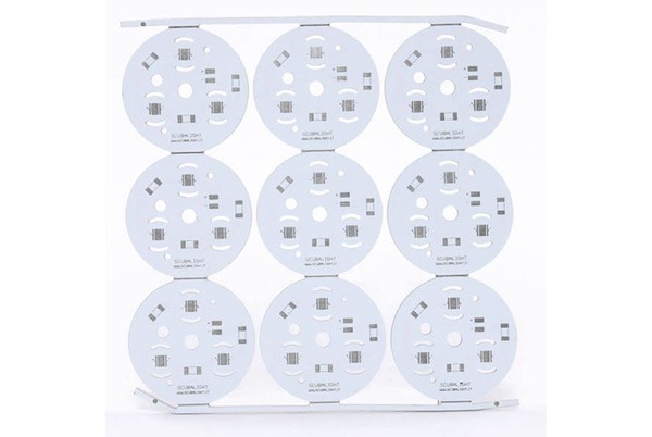
Metal Core Printed Circuit Boards (MCPCBs) are widely used in the following key areas due to their excellent thermal performance and reliability:
- LED Lighting: High-power spotlights, general lighting, and backlight modules
- Automotive Electronics: Electronic control systems and power management modules for electric/hybrid vehicles
- Power Electronics: Motor drives, solid-state relays, and high-frequency power equipment
- New Energy: Solar inverters and photovoltaic control systems
- Industrial Control: High-precision motion controllers and automation equipment drive systems
About TOPFAST
Headquartered in China, TOPFAST is a one-stop PCB solution provider specializing in rapid prototyping and small-batch manufacturing. We focus on overseas markets and are committed to providing professional and reliable PCB manufacturing services to global customers.
Our Advantages:
- Professional Expertise: Specializing in metal core PCBs, delivering high-quality manufacturing services
- Efficient Delivery: Strictly adhering to our “high quality, fast delivery” service standard
- Customer Trust: Earning high international market recognition through consistent product quality and on-time delivery commitments
TOPFAST remains committed to customer satisfaction as our core principle, striving to become the most trusted PCB partner for global clients.
Summary
Metal Core Printed Circuit Boards (MCPCB) represent a core technology in modern electronic thermal management. By combining metal substrates (such as aluminum and copper) with highly thermally conductive dielectric layers, they achieve heat dissipation efficiency far superior to traditional FR-4 substrates. Widely used in high-power applications like LED lighting, automotive electronics, new energy, and industrial control, MCPCBs enhance device reliability and power density while effectively addressing thermal management challenges in high-temperature environments. With the development of emerging technologies like 5G and electric vehicles, metal core PCBs continue to make breakthroughs in material innovation (such as ceramic substrates and composite materials) and process optimization (such as embedded heat dissipation), providing more efficient thermal solutions for high-power electronic devices.
Frequently Asked Questions About MCPCB
A: Thermal Performance: The thermal conductivity of metal core PCBs (1-7 W/m·K) is significantly higher than that of FR-4 (0.3-0.4 W/m·K), improving heat dissipation efficiency by approximately 8-9 times.
Structural Strength: Metal core boards (e.g., aluminum, copper) offer higher rigidity and better resistance to vibration and impact.
Cost and Process: Metal core PCBs are more expensive and require specialized processes (e.g., metal core cutting, insulation treatment), whereas FR-4 PCBs benefit from mature processes and lower costs.
A: Yes, but the design must meet the following conditions:
Symmetrical Structure: The number of layers on both sides of the metal core must be consistent (e.g., a 6-layer metal core PCB has a metal core at the center with 3 layers on each side).
Insulation Treatment: A high-thermal-conductivity dielectric layer must isolate the metal layer from the circuit layer to prevent short circuits.
Process Limitations: Drilling must avoid residual metal debris, and the hole walls require insulation filling.
A: Aluminum-Based Boards:
Advantages: Lower cost, lightweight, and thermal conductivity (1-6 W/m·K) suitable for most applications (e.g., LED lighting, power modules).
Applicable Scenarios: Medium to low-power heat dissipation requirements.
Copper-Based Boards:
Advantages: Excellent thermal conductivity (~388 W/m·K), suitable for high-power devices (e.g., automotive LiDAR, high-power motor drivers).
Disadvantages: Higher cost, heavier weight, and require anti-oxidation treatment.
A: Yes, the following solutions can further improve heat dissipation:
Heat Sinks: Increase the heat dissipation area through fin structures, available in passive (natural convection) and active (air/liquid cooling) types.
Heat Pipes/Vapor Chambers: Embedded heat pipes (equivalent thermal conductivity >5000 W/m·K) or vapor chambers (temperature difference ≤2°C) for localized high-temperature areas.
Thermal Interface Materials: Such as thermal grease or ceramic-filled polymers, to fill micro-gaps between chips and the metal core board.
A: Electrical Insulation: The metal core must be isolated from the circuit layer by a dielectric layer (e.g., aluminum oxide) to prevent short circuits.
Hole Size and Spacing:
Component holes ≥0.8mm, vias 0.3-0.8mm, and the spacing between hole walls and the metal core must be ≥0.5mm.
If the spacing between hole walls is <1.15mm, full slots must be created to avoid stress concentration.
Thermal Expansion Matching: The coefficient of thermal expansion (CTE) of the metal core and component materials should be similar to prevent solder joint cracking due to thermal stress.