Table of Contents
Technical Specifications of 5 Pin Relay
Basic Structure
A standard five-pin relay consists of:
- Electromagnetic Mechanism: 2 coil terminals (control input)
- Contact System:
- Common (COM)
- Normally Open (NO)
- Normally Closed (NC)
Working Principle
- Electromagnetic relays are available in DC and AC types.
- Operation Process:
- Activation Phase: When rated voltage/current is applied to the coil, electromagnetic force overcomes spring resistance, moving the armature.
- Contact Action: Armature movement closes NO contacts and opens NC contacts.
- Reset Phase: Upon de-energization, spring force returns the armature to its initial position, resetting the contacts.
Relay Classification
- Reed Relay
- Sealed construction
- Dual function: Contact & magnetic circuit
- Typical applications: Precision measurement devices
- Time Delay Relay
- Delayed output response after input signal change
- Delay range: Milliseconds to hours
- Control types: On-delay / Off-delay
- Solid-State Relay (SSR)
- No moving parts
- Opto-isolation technology
- Features: Long lifespan, spark-free operation
- Temperature Relay
- Temperature-sensitive actuation
- Setpoint accuracy: ±1°C
- Applications: Overheat protection systems
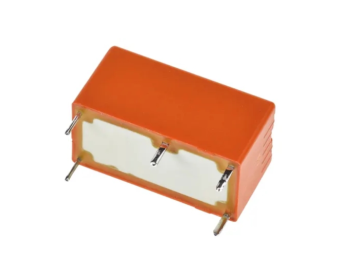
PE Series Latching Relay Specifications
- General Characteristics
- Type: Single-coil polarized latching (bistable)
- Mechanical endurance: 10⁶ operations
- Electrical endurance: 10⁵ operations (rated load)
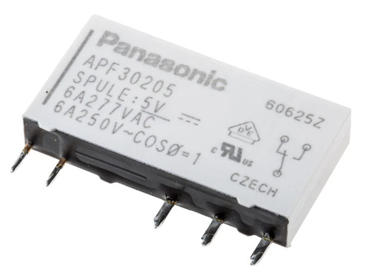
- Electrical Parameters
- Coil sensitivity: 200mW
- Contact rating: 5A / 250V AC
- Dielectric strength: 4000V AC (coil-to-contact)
- Environmental Specifications
- Operating temperature: -40°C to +85°C
- Storage temperature: -55°C to +125°C
- Protection class: Compliant with IEC 61810-1
- Mechanical Specifications
- Dimensions: 20(L) × 10(W) × 10(H) mm
- Mounting: PCB-mounted
V. Safety Certifications
- VDE Certified (EN 61810 series standards)
- RoHS Compliant
- CE Marked
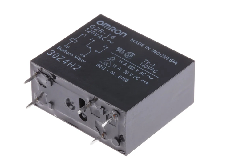
12V Single-pole, Double-throw Relay
This is a 12V single-pole, double-throw relay (single-pole, double-throw). Typically, I use these types of relays to manage AC loads. The specifications of the relay are shown at the top. This relay can be controlled using 12VDC, the voltage used to excite the relay coil. This voltage is completely isolated from the voltage supplied to the relay’s common contacts and normally closed or open contacts.
It can handle AC load currents up to 250A at 7VAC, 125A at 10VAC, and 120A at 12VAC. The relay can also manage DC loads up to 28VDC and 10A.
How does the 5-pin relay work?
When the manual switch is not available, the relay’s insulated coil automatically flips the changeover switch. Thus, it acts as a control circuit. When energized, relays often use transistor-like components to carry electrical loads. However, there is a type known as electromechanical relays. These relays are easy to understand.
A relay uses a low voltage to convert an electromagnet into a magnetic field. It also contains a contact switch for controlling the magnetic circuit. When the held heading is within the magnetic field, the relay works mainly like flipping a button with the contact in place.
Because of the way the home switch works, it will always stay the way you left it. If you turn it on, it will remain on until you turn it off, and vice versa. On the other hand, a relay coil works differently because it requires electromagnetic action for its basic activity. During deactivation, the electrical switch goes slack when the magnets present are in a magnetic field. It says that if the rated current is off, the external circuit will turn on; otherwise, the device will malfunction.
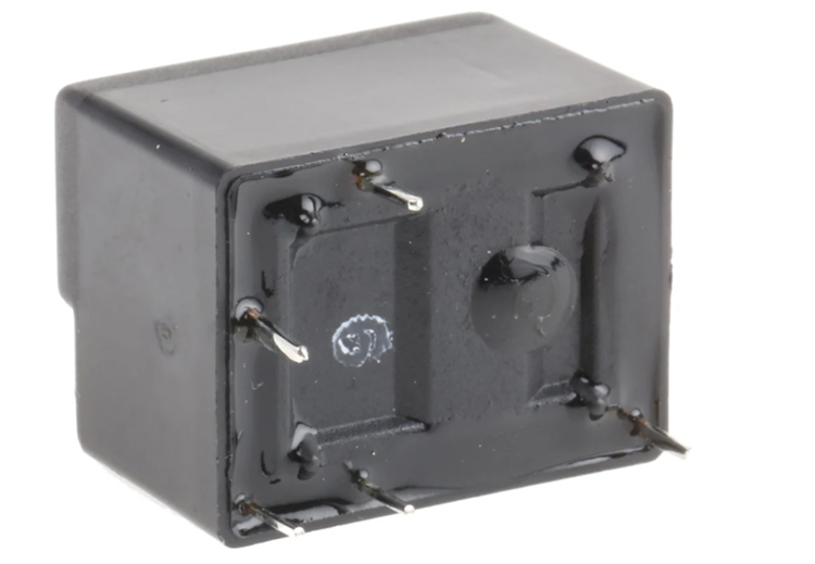
Standard 5-pin relays feature the following pin configuration
- A1/A2: Control terminals forming the electromagnetic coil circuit
- COM: Common contact terminal for the controlled main circuit
- NO: Normally Open contact (conducts with COM when energized)
- NC: Normally Closed contact (conducts with COM when de-energized)
Note: Some models may label NO as “13/14” and NC as “11/12” with identical functionality
Wiring Configurations
1. Single-Channel Control
- Wiring:
- COM → Load power terminal
- NO → Load input
- NC → Left open or connected to an indicator
- Operation:
- Energized: COM-NO closes to power load
- De-energized: COM-NC closes to cut power
2. Dual-Channel Switching
- Wiring:
- COM → Common power input
- NO → Device A power input
- NC → Device B power input
- Applications:
- Automatic power source switching
- Primary/backup device selection
3. Multi-Channel Control
- Implementation:
- Parallel connection of multiple relays’ COM terminals
- Independent NO terminals for separate loads
- Advantages:
- Single control signal triggers multiple devices
- Scalable for additional control loops
Typical Applications
1. Smart Home Systems
- Remote control of HVAC/water heaters
- Automated lighting management
- Security device activation
2. Industrial Automation
- PLC output signal amplification
- Motor forward/reverse control
- Production line sequencing
3. Automotive Electronics
- High-current load control (headlights, cooling fans)
- Safety cutoffs (overload protection)
- Comfort systems (power windows, seat heaters)
Selection & Usage Guidelines
- Electrical Compatibility
- Coil voltage must match the control signal
- The contact rating should exceed the load current
- Safety Compliance
- Maintain creepage distance for high-voltage use
- Add flyback diodes for inductive loads
- Reliability Measures
- Avoid prolonged partial contact engagement
- Regularly inspect contact oxidation
Tip: Verify contact states with a multimeter before final wiring
Technology Trends
Evolution of modern 5-pin relays:
- Energy-efficient coil designs
- Modular integration (with drive circuits)
- Smart features (status feedback)
Properly configured 5-pin relays enable flexible and robust control systems. For optimal performance, select IEC/GB-compliant models suited to specific applications.