Table of Contents
What is an Inductor
An inductor is a component that converts electrical energy into magnetic energy and stores it. The structure of an inductor is similar to that of a transformer, but it has only one winding. The inductor has a certain inductance, which only hinders the change of current. If the inductor is in a state where no current passes through it, it will attempt to impede the flow of current through it when the circuit is open; if the inductor is in a state where current passes through it, it will attempt to maintain the current unchanged when the circuit is open. Inductors are also known as chokes, reactors, and dynamic reactors.
What are the types of inductors?
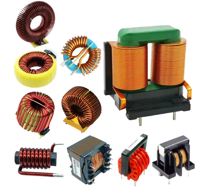
There are various types of inductors, mainly including the following:
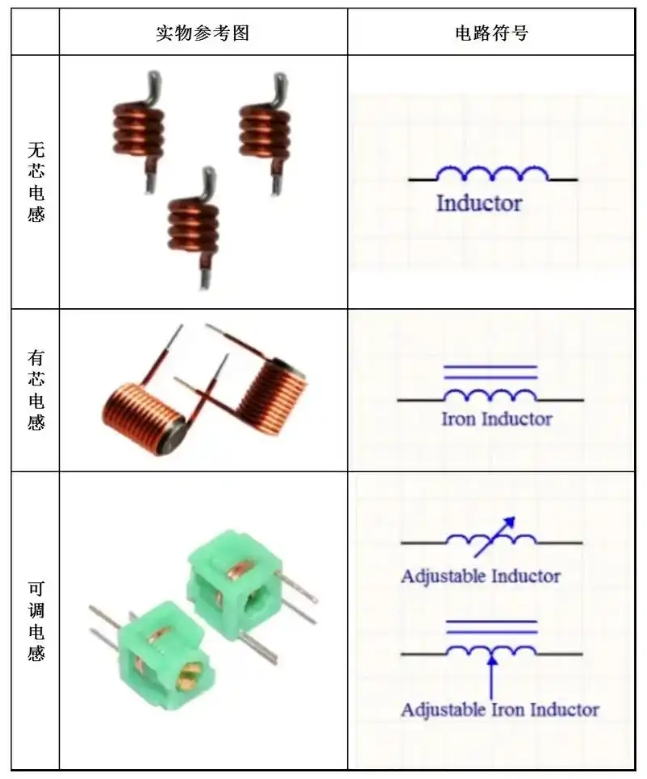
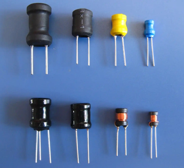
Small inductors: usually fixed on the circuit, directly wound with enameled wire on the core and bar, suitable for smaller electronic components in the circuit
Adjustable Inductors: The inductance can be adjusted by changing the position of the core and bars or by sliding a switch.
Current-blocking inductors: In circuits that impede the passage of AC current, generally using E-type cores and rods, they can be installed with an appropriate gap to prevent the passage of large DC current caused by magnetic saturation.
Fixed inductors: Coils are sealed in the shell, with small size, light weight, solid structure, stable inductance, and easy to use and install.
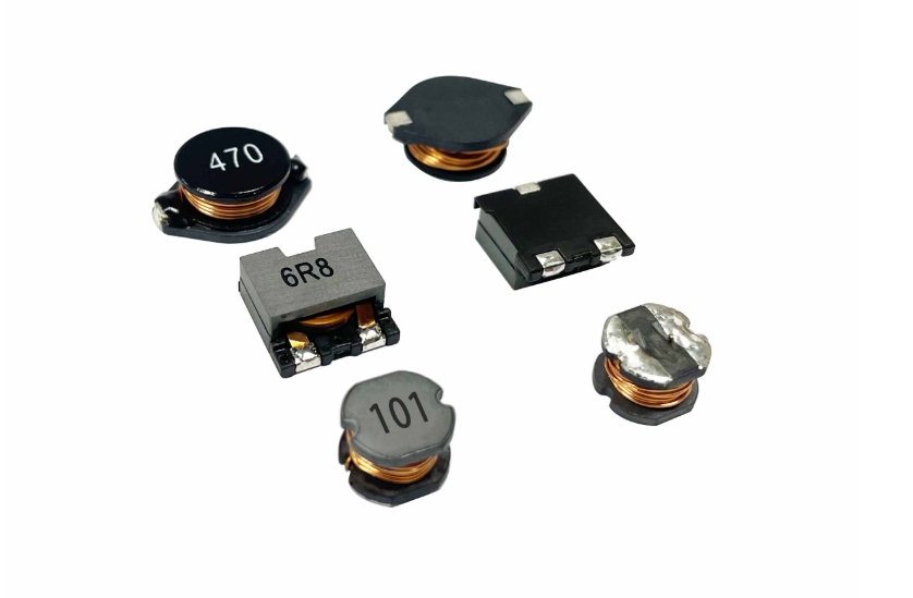
Chip inductors: including small power chip inductors and high-power chip inductors, the former appear, and chip ceramic capacitors similar to the latter are commonly used in power supply circuits in the filtering and energy storage circuits.
Color ring inductors: marked by three or four color rings to indicate the inductance, the labeling method is similar to the of ordinary color ring resistors.
Power Inductors: These include core inductors and wirewound inductors, the former through energy storage and filtering, and the latter through coarse-diameter enameled wire wound into multiple coils, usually used in filtering circuits.
Common mode inductors: Used to filter common mode electromagnetic interference, effectively inhibiting the high-speed signal lines generated by electromagnetic waves radiated outward to enhance the system’s anti-jamming capability.
How Inductors are Constructed
Inductors are generally composed of a skeleton, windings, shielding, encapsulation material, magnetic core, or iron core, etc..
1: skeleton The
skeleton refers to the support of the winding coil. Some of the larger fixed inductors or adjustable inductors (such as oscillating coils, choke coils, etc.), most of the enameled wire (or yarn wrapped wire) around the skeleton, and then the core or copper core, iron core, etc. into the inner cavity of the skeleton, to improve its inductance. The skeleton is usually made of plastic, plastic wood, or ceramic, and can be made into different shapes according to the actual needs. Small inductors (e.g., color-coded inductors) generally do not use bobbins, but instead wind enameled wire directly onto the core. Hollow inductors (also known as stripped coils or hollow coils, mostly used in high-frequency circuits) do not use the core, skeleton, and shielding, etc., but are first wound in the mold and then removed from the mold, and there will be a certain distance between the coils.
2: Winding
Winding is a set of coils with a specified function, which is the basic component of an inductor. There are single-layer and multi-layer windings. Single-layer winding and has a dense winding (winding wire circle by circle) and between the winding (winding between each circle of wire are separated by a certain distance) in two forms; multi-layer winding has a layered flat winding, chaotic winding, honeycomb winding method, and so on.
3: Magnetic core and magnetic bar
Magnetic core and magnetic bar generally use nickel-zinc ferrite (NX series) or manganese-zinc ferrite (MX series) and other materials, it has “I” shape, column, cap, “E” shape, can shape and other shapes.
4: Core
The core material is mainly silicon steel sheet, Po Mo alloy, etc., and its shape is mostly “E” type.
5: Shield
To avoid some inductors in the work of the magnetic field generated by other circuits and components affecting the normal operation of the increase of the metal screen cover (such as semiconductor radio oscillator coil, etc.). Inductors with shielding will increase the loss of the coil and reduce the Q value.
6: packaging materials
Some inductors (such as color code inductors, color ring inductors, etc.) after wound with encapsulation materials to seal up the coils and cores. The encapsulation material is plastic or epoxy resin.
Inductance Symbols
The symbol of inductance is unified in electrical engineering and physics with a capital letter L. Its international unit is Henry (H), and commonly derived units include millihenry (mH), microhenry (μH), and nanohenry (nH), and the conversion relationship is:
1H = 10³mH = 10⁶μH = 10⁹nH.
Inductance formula
Impedance formula: Z= R+j ( XL-XC). Impedance Z= R+j ( XL -XC). Where R is resistance, XL is inductive reactance and XC is capacitive reactance. If ( XL – XC) \u003e 0, it is called an “inductive load”; conversely, if ( XL – XC) \u003c 0, it is called a “capacitive load”. The inductive reactance of an inductor and the capacitive reactance of a capacitor are three types of complexes that are collectively called “impedances” and are written as mathematical equations.
In an alternating circuit (high school level), the effect of temperature is not taken into account.
Resistance:R=ρL/S does not vary with the frequency of the alternating current.
Inductance: Inductive reactance XL=2πfL increases as the frequency of the alternating current increases.
Capacitor: Capacitive reactance XC=1/2πfL decreases as the frequency of the alternating current increases.
In a parallel circuit of resistance, inductance, and capacitance
1/R total = 1/R + 1/XL + 1/XC.
Electrical Explanation
Impedance is a physical quantity that indicates the performance of a component or the electrical properties of a section of a circuit. The ratio of the peak voltage (or rms) Um at the ends of a passive circuit to the peak current (or rms) Im through the circuit is called impedance, and is expressed as z in ohms (Ω). In the case of a certain U, the larger z is the smaller I. Impedance has a limiting effect on the current.
In an electric current, the effect of an object in obstructing the current is called resistance. Except for superconductors, all substances in the world have resistance; only the magnitude of the resistance value is different. Substances with very low resistance are called good conductors, such as metals; substances with very high resistance are called insulators, such as wood and plastic. There is also an in-between conductor called a semiconductor, and a superconductor is a substance with a resistance value equal to zero, although it requires a low enough temperature and a weak enough magnetic field for its resistivity to be zero.
In direct current and alternating current, resistance to the two currents are hindered; as a common component, in addition to resistance and capacitance and inductance, both of which on a role of alternating current and direct current are not as resistive as the role of hindrance. Capacitance is “isolated through the cross”, that is, the DC has the role of isolation, that is, DC can not be passed, while the AC can be passed, and with the increase in capacitance value or AC power increases, capacitance on the AC power of the obstruction of the role of the smaller, this obstruction can be interpreted as “resistance”, but not the same as “resistance”, but not the same as “resistance”. ”, but not the same as resistance, this is a kind of reactance, reactance and resistance units, collectively referred to as “impedance”. Of course, accurately, “impedance” should have three parts, in addition to these two, is the “inductive resistance”. Inductive reactance is the inductance of the current obstruction, and capacitance is different, the inductance of the direct current without obstruction (rigorously speaking, in the brief few milliseconds before the saturation of the power supply, but also obstruction) on the exchange of obstruction, inductive reactance and capacitive reactance, and resistance units are the same as the unit is ohm.
Impedance Mechanics Explained
The concepts of impedance, resistance, and impedance are not only found in electrical circuits, but also in vibrating systems, where impedance, also denoted by Z, is a complex number, and a phase (Phasor), containing Magnitude and Phase/Polarity. it consists of Resistance and Reactance. Resistance is the consumption of energy, while reactance is the conservation of energy. In a vibration system, the resistance generated by mass is mass resistance, while the resistance generated by stiffness is stiffness resistance.
The Role of Inductors
Inductors (inductors) are important passive components in PCBs. Their core function is based on the principle of electromagnetic induction, which realizes a variety of applications by storing energy in a magnetic field and impeding current changes.
- Energy storage and filtering
Conversion of electrical energy into magnetic energy storage: Inductors can convert electrical energy into magnetic energy storage and release the energy when the current changes. This feature is used to stabilize the output voltage in switching power supplies.
Smoothing current fluctuation: Combined with capacitors to form an LC filter, it can suppress high-frequency noise in the power supply, for example, filtering out AC ripple in a DC power supply. - Obstructing AC power (blocking traffic straight)
Short circuit to DC: DC passes through the inductor with almost no obstruction, showing a path condition.
Inductive impedance to AC: The inductor produces inductive impedance when AC passes through; the higher the frequency the stronger the impedance effect. This characteristic is used in the design of RL low-pass filters and RL high-pass filters. - Voltage/current conversion and impedance matching
Transformer application: change the voltage and current through the coil turns ratio, for example, input 220V can output 110V, but the current changes inversely (power conservation).
RF circuit matching: In wireless communications, inductors are used to adjust circuit impedance and optimize signal transmission efficiency. - Resonance and frequency selection
LC resonant circuit: Combined with capacitors to form a resonant circuit, used for radio tuning, frequency selection, etc., such as frequency selection filters for radios. - Other key roles
Choke: prevent high-frequency interference (EMI) through, to protect sensitive components.
Current Sensing: Use the magnetic field generated by the current change to monitor the circuit current strength.
Do inductors have polarization?
Inductors are not polarized. An inductor is a passive electronic component, mainly consisting of a coil and a magnetic core, and its operating principle is based on the phenomenon of electromagnetic induction rather than on the phenomenon of dielectric polarization. Therefore, inductors have no polarization characteristics
Operating Principle and Characteristics of Inductors
The operating principle of an inductor is based on the phenomenon of electromagnetic induction. When an electric current passes through the coil of an inductor, a magnetic field is generated that stores energy. When the current changes, the magnetic field also changes, resulting in an electric potential (EMF), which is the basic operating principle of an inductor. Due to the internal structure and material properties of an inductor, it is not polarized.
Do inductors have resistance?
Inductors themselves have wire resistance, but an ideal inductor has zero resistance.
Inductors contain both inductive properties (inductive reactance) and wire resistance components in practical applications. The details are analyzed as follows.
- Difference between an ideal inductor and a real inductor
Ideal inductor: Theoretically, only magnetic energy is stored, there is no energy loss, and its DC resistance is zero, which is only manifested as inductive reactance.
Real Inductor: Due to the resistance of the wire used to wind the coil (e.g. copper wire), a real inductor will exhibit DC resistance (DCR), which is the ohmic resistance of the wire itself, and will result in energy loss in the form of heat. - Impact of Resistance on Inductor Performance
DC Circuit: Inductors exhibit a wire resistance (DCR), which is usually small but affects circuit efficiency (e.g., power loss in power supply filtering).
AC circuits: The total impedance Z of an inductor is determined by the combination of the inductive impedance XL and the resistance R. The inductive impedance dominates at high frequencies and the resistance R at low frequencies. The inductive impedance dominates at high frequencies, and the effect of resistance is more significant at low frequencies. - Design Considerations for Practical Applications
High-frequency circuits: Inductors with low DCR are usually chosen to minimize losses, e.g., by using thicker wires or low-resistivity materials (e.g., silver plating).
Power inductors: need to balance inductance and DCR to avoid overheating (e.g., ferrite core inductors are commonly used in high-frequency, low-loss scenarios).
What to pay attention to is the layout of PCB inductors
PCB inductor layout should pay attention to the location planning, copper foil processing, the following layer avoidance, pin spacing, and heat dissipation design.
Location Planning
Inductors should be placed as close as possible to the relevant chips (e.g., ICs for DC-DC switching circuits) to shorten the current path and reduce interference and loss.
In RF or high-frequency circuits, prioritize the layout of critical inductors and distance them from other sensitive modules (e.g. analog circuits) to avoid signal crosstalk.
Copper Foil Area Control
The area of copper foil for inductor connection should be moderate, too large may introduce antenna effect and increase EMI risk; too small may cause heat generation or damage due to excessive current. It is recommended to refer to the design of current tolerance characteristics (e.g. 1 ounce board for every 1A current corresponds to 1mm line width).
Lower Layer Avoidance
It is forbidden to arrange the ground (GND) layer or signal line directly below the inductor, otherwise, the magnetic lines of force passing through the conductor layer will cause eddy currents, resulting in decreased inductance or signal interference. If wiring is necessary, use a closed-circuit inductor and verify with real-world measurements.
Pin spacing and wiring
Inductor pin spacing should not be too close to avoid high-frequency noise coupled to the output through parasitic capacitance. The wiring can be arranged in a “zigzag” arrangement, with ground on both sides to enhance isolation.
Heat dissipation and process compatibility
High-power inductors need to reserve space for heat dissipation, to avoid being close to the thermal components, if necessary, the back of the window or increase the number of heat sinks.
Consider production process requirements, such as plug-in inductors, need to reserve enough space for soldering, and SMD inductors’ centralized layout to improve efficiency.
Key design tool reference:
RF impedance calculation tool SI9000 can assist in the design of line width and spacing to meet the requirements.
For high-frequency noise-sensitive scenarios, software simulation tools (e.g., HFSS) can be used to verify the layout of a reasonable
Application Scenarios of Inductors
Inductors have a wide range of applications in many fields and scenarios, mainly including the following:
Power supply circuits: In switching power supplies, inductors act as key energy storage components, stabilizing the output voltage by storing and releasing energy. For example, in step-down switching power supplies, inductors store energy when the switching tube conducts and release energy when it cuts off, thus stabilizing the output voltage and reducing the power supply output ripple. In addition, inductors are used to step up or step down in DC-DC converters, and are commonly used to boost the output voltage of photovoltaic panels and other applications.
Communication: In RF circuits, inductors are used for energy storage and filtering, and often form resonant circuits with capacitors to improve power transfer efficiency. For example, in RF power amplifiers, inductors are used in conjunction with capacitors to make the amplifier work efficiently at a specific frequency. This is critical for signal transmission and reception in wireless communication devices such as cellular base stations and cell phones, helping to improve communication quality and coverage.
Automotive electronics: In electronic fuel injection systems for automobiles and motor drive systems for hybrid/electric vehicles, inductors store electrical energy and quickly release it during high-torque startup or acceleration to enhance motor power performance. In addition, inductors are used to suppress transient voltages and currents on power lines, protecting electronic equipment from voltage spikes.
Industrial field: In the soft start and speed control of industrial motors, inductors limit the starting current by storing and slowly releasing energy, avoiding excessive impact on the power grid when the motor starts. In frequency conversion speed control systems, inductors work with other components to achieve smooth regulation of motor speed.
Renewable energy: In wind power and photovoltaic power generation systems, inductors are used for energy storage and release to improve system stability and efficiency.
Other applications: Inductors are also used in modems to effectively filter and isolate signals to ensure clear signal transmission. In addition, inductors are widely used in resonant circuits, chokes, and current sensing.