Table of Contents
What is a Capacitor
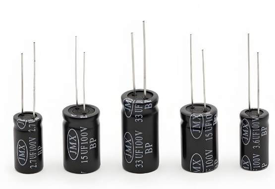
A capacitor is an element that stores electricity and electrical energy (potential energy). A conductor surrounded by another conductor, or a conductor in which the electric field lines emanating from one conductor all terminate in the other is called a capacitor. A capacitor stores charge when a voltage is applied between the two extreme plates of the capacitor. The capacitance of a capacitor is numerically equal to the ratio of the charge on one conducting plate to the voltage between the two plates. The basic unit of capacitance of a capacitor is the farad (F). The letter C is usually used in circuit diagrams to denote capacitive elements.
Capacitor Symbol
Internationally standardized, the amount of charge that can be stored in a capacitor when a 1-volt DC voltage is applied to it is the capacitance (i.e., the amount of electricity per unit voltage) of the capacitor, denoted by the letter C. The basic unit of capacitance is the farad (F), which is the voltage ratio between the two electrodes. The basic unit of capacitance is the farad (F). In 1-volt DC voltage, if the capacitor stored charge for 1 coulomb, the capacitance is set at 1 farad, farad with the symbol F, 1F = 1C/V. In practice, the capacitance of the capacitor is often much smaller than 1 farad, commonly used smaller units such as millifarads (mF), microfarads (μF), nano-farads (nF), pico-farads (pF), and so on, the relationship between: 1 microfarad equal to a millionth of a farad; 1 pifa is equal to one-millionth of a microfarad, i.e.: 1 farad (F) = 1,000 millifarads (mF); 1 millifarad (mF) = 1,000 microfarads (μF); 1 microfarad (μF) = 1,000 nanofarads (nF); 1 nanofarad (nF) = 1,000 pifaads (pF); i.e.: 1F = 1,000,000 μF; 1 μF = 1,000,000 pF.
Capacitors What are the uses of
Capacitors play an important role in circuits such as tuning, bypassing, coupling, and filtering. In a DC circuit, a capacitor is the equivalent of a circuit breaker. A capacitor is a component capable of storing charge and is one of the most commonly used electronic components.
●Coupling: Capacitors used in coupling circuits are called coupling capacitors, and are used in a large number of resistive-coupled amplifiers and other capacitively coupled circuits to isolate the direct current from the alternating current.
●Filtering: Capacitors used in filtering circuits are called filtering capacitors, and are used in power supply filtering and various filter circuits. Filtering capacitors remove signals in a certain frequency band from the total signal.
●Decoupling: Capacitors used in decoupling circuits are called decoupling capacitors, which are used in DC voltage supply circuits of multistage amplifiers to eliminate harmful low-frequency cross-links between each stage of the amplifier.
High-frequency cancellation: A capacitor used in a high-frequency cancellation circuit is called a high-frequency cancellation capacitor. In an audio negative-feedback amplifier, this capacitor circuit is used in order to cancel possible high-frequency self-excitation to eliminate possible high-frequency whistling in the amplifier.
Resonance: The capacitor used in the LC resonant circuit is called a resonant capacitor, which is required in both LC parallel and series resonant circuits.
Bypass: Capacitors used in bypass circuits are called bypass capacitors. If a certain band of signals needs to be removed from a signal in a circuit, a bypass capacitor circuit can be used, and depending on the frequency of the signal to be removed, there are full-frequency domain (all AC signals) bypass capacitor circuits and high-frequency bypass capacitor circuits.
●Neutralization: A capacitor used in a neutralization circuit is called a neutralization capacitor. These neutralizing capacitor circuits are used in radio high-frequency and intermediate-frequency amplifiers, and television high-frequency amplifiers to eliminate self-excitation.
●Timing: Capacitors used in timing circuits are called timing capacitors. Timing capacitor circuits are used in circuits that require time control by charging and discharging capacitors, which control the size of the time constant.
●Integration: A capacitor used in an integration circuit is called an integration capacitor. This integral capacitor circuit is used in synchronous separation circuits for potential field scanning to remove the field synchronization signal from the field composite synchronization signal.
●Differential: A capacitor used in a differential circuit is called a differential capacitor. This differential capacitor circuit is used in a trigger circuit to obtain a spike trigger signal from various types of (mainly rectangular pulse) signals.
●Compensation: A capacitor used in a compensation circuit is called a compensation capacitor, and this low-frequency compensation capacitor circuit is used in the bass compensation circuit of a cassette deck to boost the low-frequency signal in the playback signal, and there is also a high-frequency compensation capacitor circuit.
Bootstrap: The capacitor used in the bootstrap circuit is called a bootstrap capacitor, and this bootstrap capacitor circuit is used in the output stage circuit of commonly used OTL power amplifiers to boost the positive half-cycle amplitude of the signal by a small amount through positive feedback.
● Crossover: The capacitor in a crossover circuit is called a crossover capacitor. In the speaker crossover circuit of a loudspeaker, a crossover capacitor circuit is used to enable the high-frequency loudspeaker to operate in the high-frequency band, the mid-frequency loudspeaker to operate in the mid-frequency band, and the low-frequency loudspeaker to operate in the low-frequency band.
● Load capacitance: This is the effective external capacitance that determines the resonant frequency of the load together with the quartz crystal resonator. The standard values of load capacitance are 16pF, 20pF, 20pF, 20pF, 20pF, 20pF, 20pF and 20pF.
How Capacitors Work
A capacitor is an electronic component capable of storing an electrical charge, and its principle of operation is based on the accumulation and release of charge.
- Basic construction
A capacitor consists of two conductive electrodes (usually metal plates) with an insulating medium (e.g. air, plastic, ceramic, etc.) in between. This structure is similar to a “sandwich”, the charge can be accumulated in the electrodes, but can not flow directly through the insulating medium. 2. charging process - Charging process
When a capacitor is connected to a power supply, the charging process begins:
The positive pole of the power supply delivers a positive charge to one electrode, and the negative pole delivers a negative charge to the other electrode.
Due to the barrier of the insulating medium, the charge cannot pass through directly, but can only accumulate on the respective electrodes.
With the accumulation of charge, the potential difference between the electrodes gradually increases until it is equal to the supply voltage, and the charging process is over. - Discharge Process
When a capacitor is disconnected from the power supply and connected to a load, the discharge process begins:
The charge on the electrodes forms a current through the load under the action of the electric field force.
As the charge is released, the potential difference between the electrodes decreases until it reaches zero and the discharge process ends. - Capacitance and Electric Fields
The capacitance (C) of a capacitor indicates its ability to store charge and is calculated by the formula:
C=Q/, Capacitor Equation
Capacitance Determinant:C=εS/(4Tkd)
Capacitance Calculation: C=Q/U
where ϵ is the dielectric constant of the insulating medium, S is the electrode area, and d is the distance between the electrodes. The electric field plays a central role in the charging and discharging process, driving the movement of charges.
The energy stored in a capacitor is electric field energy, which is essentially the potential energy stored in the electric field between the conductor plates. When a capacitor is charged, charges accumulate under the influence of the electric field, converting electrical energy into electric field energy; during discharge, the electric field energy is released as other forms of energy.
Formulas for Calculating Capacitor Energy
The energy of a capacitor can be calculated using the following three equivalent formulas, depending on the known parameters (capacitance C, voltage U, or charge Q):
- Based on Voltage and Capacitance:

This formula shows that the energy is proportional to the capacitance and the square of the voltage, making it suitable for scenarios where the charging voltage is known.
2. Based on Charge and Voltage:

This calculates energy through the potential difference during charge transfer, often used to analyze the charging process.
3. Based on Charge and Capacitance:

This is applicable when the charge and capacitance are known, such as in the energy calculation of an isolated conductor.
Key Influencing Factors
- Capacitance: Determined by the plate area (S), spacing (d), and permittivity (ε) (where C=εS/dC=εS/d). Increasing the plate area or reducing the spacing enhances energy storage capacity.
- Operating Voltage: Energy is proportional to the square of the voltage, but exceeding the rated voltage may cause breakdown.
- Frequency Characteristics: At high frequencies, capacitance decreases, which may affect energy storage efficiency.
How to Increase Capacitor Energy
To effectively increase the electric field energy storage of capacitors, the first task is to select capacitors. We need to pay attention to the capacitance and voltage of the capacitor and prefer large-capacity, high-voltage capacitors with good voltage resistance and low-loss characteristics to ensure their stability and reliability. Secondly, energy storage can be increased directly by raising the operating voltage or increasing the capacitance of the capacitor. For example, by connecting two capacitors with the same capacitance in series, the total capacitance can be doubled, thus significantly increasing the energy of the electric field. In addition, the series connection of capacitors not only enhances the electric field energy but also realizes multiple functions such as power factor correction and filtering, which are widely used. In summary, through careful selection of capacitors, reasonable enhancement of its energy storage, and clever use of series connection technology, can significantly enhance the capacitor’s electric field energy storage capacity, for the optimization of circuit performance and stability to lay a solid foundation.
What is the life expectancy of a capacitor
- The general range of capacitor life
Generally speaking, power capacitors are designed for a life of 8 to 12 years. However, this does not mean that all capacitors need to be replaced within this timeframe, as the actual service life can be affected by a variety of factors. For example, ambient temperature, operating voltage, loading conditions, and the quality of the capacitor itself will all have an impact on its life. - Key factors affecting the life of capacitors
Ambient temperature: High temperature accelerates the evaporation and decomposition of the electrolyte inside the capacitor, thus reducing its capacity and voltage value. In addition, high temperatures will also lead to the aging of the insulating material inside the capacitor, further shortening its life.
Load conditions: If a capacitor is operated under overload for a long period of time, it may lead to overheating or malfunction, thus shortening its service life.
Capacitor quality: High-quality capacitors usually have better insulating materials, stricter manufacturing processes, and more reliable packaging, resulting in greater resistance to aging and durability. - How to extend the life of capacitors
To extend the life of capacitors, the following measures can be taken:
Maintain a suitable working environment and temperature range, and avoid high temperature, humidity, and corrosive environments.
Reasonable selection and design of capacitors to ensure that the voltage and load they withstand are within the appropriate range.
Regular maintenance and inspection, timely detection and treatment of abnormal conditions of capacitors, such as capacity degradation, physical damage, etc..
In summary, although the design life of capacitors is generally 8 to 12 years, the exact replacement time needs to be assessed comprehensively according to their actual operating conditions and environmental factors. By taking reasonable measures, we can effectively extend the service life of capacitors and ensure the stable operation of electronic equipment and circuits.