Table of Contents
What is a voltage sensing relay?
A voltage sensing relay is a kind of automatic control device based on voltage detection, which is mainly used to monitor the voltage change in the circuit and execute the corresponding switching action. Its working principle is through the built-in voltage detection module real-time acquisition of circuit voltage signals, when the voltage reaches the preset threshold (over-voltage, under-voltage, or a specific voltage range), the relay contacts will quickly switch state (normally open/closed), to realize the on-off control of the subsequent circuit or protection function.
Classification and Technical Features of Voltage Sensing Relays
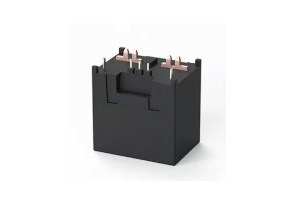
1. Electromagnetic Voltage Relay
Working Principle: Operates based on electromagnetic induction. When the input voltage reaches the threshold, the coil generates a magnetic field, driving mechanical contacts to actuate.
Key Features:
- Advantages: Simple structure, strong noise immunity, low cost, and high tolerance to short-circuit currents.
- Limitations: Slow response due to mechanical inertia (typical actuation time: 10–50 ms), lower accuracy (±5%), and contact wear.
Typical Applications: Over/under-voltage protection in power distribution systems where real-time performance is not critical.
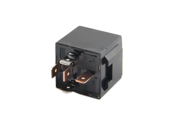
2. Static (Solid-State) Voltage Relay
Working Principle: Uses electronic circuitry for voltage sampling → signal conditioning → threshold comparison → contactless output (e.g., thyristor/relay drive).
Key Features:
- Advantages: Fast response (1–10 ms), high accuracy (±1%), no mechanical wear, and low power consumption.
- Limitations: Higher cost, weaker transient overvoltage tolerance, and requires auxiliary power.
Enhanced Features: Integrated digital display, communication interfaces (e.g., RS485), and programmable settings.
Typical Applications: Precision equipment protection, renewable energy systems, and automated control.
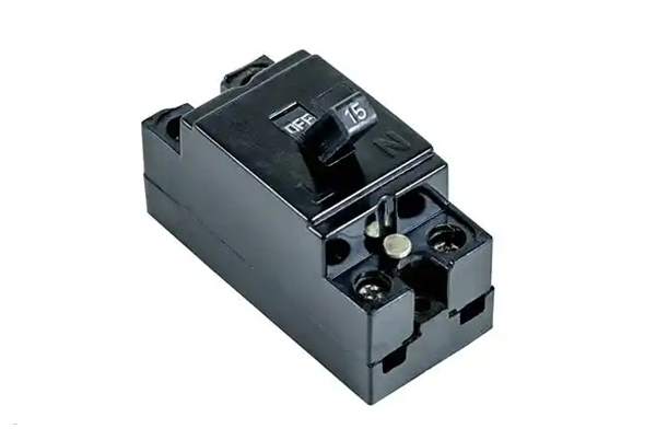
3. Hybrid Voltage Relay
Design Integration: Combines electromagnetic actuation with electronic control, merging reliability and intelligence.
Balanced Performance:
- Mechanical contacts ensure high-current switching capability, while electronics improve response time (5–20 ms) and accuracy (±2%).
- Supports extended features like LED status indication and fault self-diagnostics.
Applications: Industrial motor control, smart grids, and other scenarios requiring both reliability and advanced functionality.
Voltage Sensing Relay: Functions & Working Principle
I. Key Functions
- Overvoltage Protection
- Role: Monitors circuit voltage in real time. If voltage exceeds a preset threshold (e.g., 120% of rated value), it instantly cuts off the circuit to protect downstream equipment (e.g., motors, PLCs).
- Applications:
- Lightning strike or operational overvoltage protection in power systems.
- Preventing control module damage due to power fluctuations in industrial equipment.
- Undervoltage Lockout (UVLO)
- Role: Locks the circuit when voltage drops below a safe threshold (e.g., 80% of rated value), preventing equipment operation under unsafe conditions (e.g., motor stalling, data loss).
- Applications:
- Mitigating voltage sags in distribution systems.
- Low-voltage ride-through protection in renewable energy inverters.
- Additional Features (Model-dependent)
- Voltage imbalance protection, phase sequence detection, auto-reset delay, etc.
II. Working Principle
- Signal Detection
- Measures line voltage via voltage dividers or transformers, converting it to a processable signal (e.g., 0–5V analog).
- Threshold Comparison
- An internal comparator checks the detected voltage against preset values, triggering logic circuits (e.g., overvoltage → high output; undervoltage → low output).
- Actuation
- Electromechanical Relays: Coil generates a magnetic field, moving contacts to open/close the circuit (response time: 10–50 ms).
- Solid-State Relays (SSR): Semiconductor switches (e.g., thyristors) enable contactless operation (response time: ≤1 ms).
- Recovery
- Automatically or manually resets once the voltage normalizes (some models support an adjustable delay).
III. Technical Comparison
| Feature | Electromechanical | Solid-State (SSR) |
|---|---|---|
| Response Time | Slower (milliseconds) | Faster (microseconds) |
| Lifespan | Mechanical wear (~10^6 ops) | No contacts (~10^8 ops) |
| Noise Immunity | High | Requires spike protection |
| Load Capacity | High-current/voltage | High-frequency/small-signal |
IV. Selection Guidelines
- Threshold Accuracy: ±1% for industrial use; ±5% for consumer applications.
- Reset Mode: Auto-reset for transient faults; manual reset for safety-critical systems.
- Environment: Wide-temperature models (-40°C to 85°C) for outdoor use.
Voltage sensing relay main technical parameters
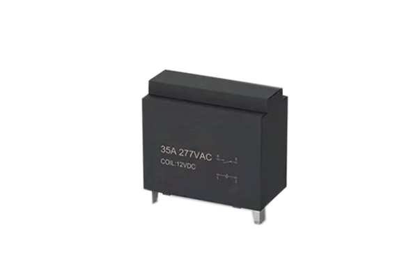
1. Electrical Characteristics
- Rated voltage: 5V, 12V, 24V, 48V, etc. (DC/AC to be labeled).
- Rated current: Maximum continuous current throughput of contacts (e.g. 10A).
- Insulation resistance: ≥100MΩ (500V DC test).
- Contact parameters:
- Type: normally open (NO)/normally closed (NC)/conversion (CO).
- Contact resistance: ≤50mΩ (tested under low load).
- Maximum switching capacity: e.g. 250V AC/30V DC.
- Load type: support resistive/inductive/capacitive loads (need to mark the derating ratio).
2. Action Characteristics
- Action voltage: Suction voltage range (e.g. 70%~110% of rated voltage).
- Release voltage: release threshold (e.g. 30% of rated voltage).
- Response time:
- Suction time: ≤10ms (typical).
- Release time: ≤5ms (typical value).
3. Mechanical and Durability
- Mechanical life: ≥10^7 times (no load switching times).
- Electrical life: ≥ 10^5 times (under rated load).
- Contact material: silver alloy/gold plating (affects arc resistance).
4. Coil Parameters (Electromagnetic Type Applicable)
- Rated Voltage: Coil operating voltage (e.g. 12V DC).
- Coil resistance: ±10% tolerance (e.g. 360Ω).
- Power consumption: Static power consumption (e.g. 0.5W).
5. Environmental adaptability
- Operating temperature: -40℃~+85℃ (industrial grade).
- Protection level: e.g. IP67 (dustproof and waterproof).
6. Safety Certification
- Compliance standards: UL, CE, RoHS, etc. (to be specified).
Selection Suggestions
- Voltage Matching: Make sure the coil voltage is compatible with the control system.
- Load capacity: Inductive loads need to leave a margin of 1.5~2 times.
- Life requirement: Prioritize solid-state relay (SSR) for high-frequency scenarios.
- Environmental factors: A High temperature/high humidity environment requires special packaging.
Voltage Sensing Relay Common Faults Q&A
1. What are the signs of contact failure? What are the causes?
Q: What happens when relay contacts stick?
A: Contact sticking is when a relay fails to release after it has been engaged, resulting in a continuously closed circuit. Common causes include:
- Presence of foreign matter between contacts (e.g., dust, oil)
- Uneven contact surface or material deterioration
- Insufficient contact pressure, resulting in poor contact or arc ablation
Q: Why does poor contact occur?
A: Poor contact is usually caused by the following problems:
- Oxidation, contamination or corrosion of the contact surface
- Wear of contacts due to long-term use
- Contact resistance increases, affecting the normal conduction of current
Q: What causes contact ablation?
A: Contact ablation may be caused by the following factors:
- Prolonged overload operation, the current exceeds the rated value
- High voltage, generating arc damage to the contacts
- Insufficient high temperature resistance of contact material
2. What are the types of coil faults? How to judge?
Q: What problems will an open coil cause?
A: When the coil is open-circuit, the relay can not be suctioned, which is manifested as:
- Broken wires inside the coil or loose terminals
- Insufficient electromagnetic force to form a closed circuit
Q: What is the danger of a short-circuited coil?
A: A short circuit in the coil will cause:
- An abnormal current increase may burn the relay
- Damage to the insulation or a short circuit between turns of the coil
Q: Under what conditions will the coil burn out?
A: Common causes of coil burnout include:
- Prolonged overload or high voltage
- Coil insulation deterioration or internal short circuit
3. Can a faulty magnetic circuit affect a relay?
Q: What problems can a bad magnetic circuit cause?
A: Abnormal magnetic circuits may affect the suction and release of a relay for reasons including:
- Worn iron cores or armatures
- Damaged non-magnetic shims
- Excessive residual magnetism that prevents the relay from resetting properly
4. What are other common failures?
Q: What are the signs of mechanical failure?
A: Mechanical failures may include:
- Stuck transmission mechanism, inflexible action
- Failure of the reaction spring, affecting the contact reset.
Q: Do environmental factors affect relays?
A: Yes, harsh environments can cause:
- Contact oxidation, corrosion (e.g. humidity, corrosive gases)
- High or low temperatures that affect relay performance
Summary
Failures of voltage sensing relays are mainly concentrated in contacts, coils, magnetic circuits, and mechanical structures etc. Proper maintenance and regular inspection can effectively reduce the occurrence of failures.
Application Scenarios
Voltage sensing relays are widely used in a variety of applications where voltage control is required, especially in power systems for over-voltage protection, low voltage blocking, and so on. For example, in generators, transformers, and transmission lines, voltage sensing relays can detect over-voltage or under-voltage conditions and cut off circuits when necessary to protect equipment and system safety. In addition, it is commonly used in industrial control, household appliances, automotive electronics, etc., to achieve precise control and protection of circuits.