Table of Contents
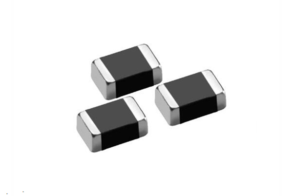
Comprehensive Guide to Testing SMD Inductors
I. Testing Principles and Importance
- Fundamentals of Inductor Testing
- Based on the AC impedance method: L=XL/(2πf), where XL is inductive reactance and f is the test frequency
- Quality factor Q reflects energy storage efficiency: Q=2πfL/R
- Error Source Analysis
- Parasitic effects (typical distributed capacitance 0.1- 0.5pF)
- Contact resistance (should be <50mΩ)
- Environmental interference (recommended shielded room for high-frequency tests)
II. Instrument Selection Guide
- Main Instrument Comparison Table
| Instrument Category | Measurement Range | Basic Accuracy | Frequency Range | Key Applications | Industry-Standard Models |
|---|---|---|---|---|---|
| Precision LCR Meter | 1nH – 100H | ±0.1% basic | 20Hz – 300kHz | Power supply filters, DC-DC converters | Keysight E4980A, Hioki IM3536 |
| RF LCR Meter | 0.1nH – 1kH | ±0.05% | 1kHz – 30MHz | RF matching networks, HF circuits | GW Instek LCR-800G, Wayne Kerr 6500B |
| Vector Network Analyzer | 0.01nH – 10H | ±0.02dB magnitude | 100kHz – 20GHz | Microwave components, Antenna systems | R&S ZNB20, Keysight PNA |
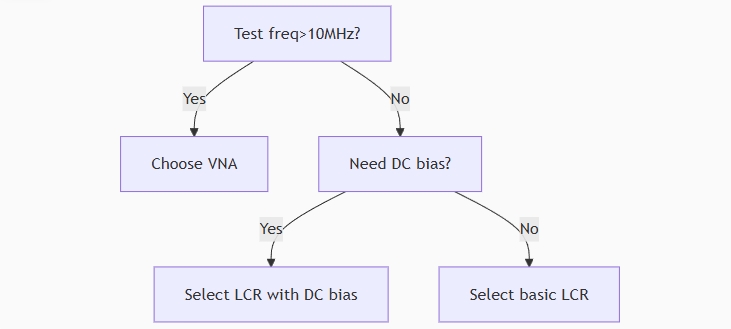
2.Selection Decision Tree
III. Standardized Testing Procedure
- Preparation Phase
- Contact surface treatment:
- Ultrasonic cleaning with isopropanol (3 minutes)
- Plasma cleaning for severe oxidation (50W, 2 minutes)
- Environmental control:
- Temperature 23±1℃ (30 min thermal stabilization)
- Humidity <45% RH
- Detailed Operation Steps
- Example for 0402 package inductor:
- Select triaxial test fixture (e.g., Cascade Microtech ACP40)
- Set test conditions:
freq = [100kHz, 1MHz, 10MHz] bias = [0mA, 10mA] - Perform contact resistance compensation (4-wire method)
- Data Acquisition Standards
- Sampling: ≥16 averages
- Stability criteria: <0.5% variation across 3 consecutive readings
IV. Advanced Testing Techniques
- Temperature Characterization
- Setup: Thermal chamber (-55℃~+150℃)
- Key parameters:
- Temperature coefficient TC=ΔL/(L0×ΔT)
- Typical value: ±30ppm/℃ (ferrite materials)
- DC Bias Characterization
- Configuration: Programmable current source (0- 10A)
- Curve analysis:
- Saturation current Isat (current at 10% L drop)
- Permeability degradation
- High-Frequency Parameter Testing
- S-parameter measurement (1MHz-20GHz)
- Key metrics:
- Self-resonant frequency (SRF)
- Q-factor frequency curve
V. Troubleshooting Guide
- Measurement Anomaly Diagnosis Table
| Symptom | Possible Causes | Recommended Solutions | Technical Notes |
|---|---|---|---|
| Reading Drift | • Poor contact (Rcontact >50mΩ) • Loose fixture • Temperature fluctuation | • Use gold-plated spring probes • Apply contact cleaner (e.g., DeoxIT D5) • Stabilize test environment (±1°C) | Contact resistance should be <20mΩ for nH-range measurements |
| Low Q Value | • Core material loss (tanδ>0.1) • Frequency near SRF • Excessive DC bias | • Test at manufacturer-specified freq • Reduce DC bias to <10% Isat • Verify core material specs | For RF apps: Q<30@100MHz indicates potential issue |
| Negative L Value | • Testing beyond SRF • Fixture capacitance (>1pF) • Ground loop issues | • Test at ≤50% of SRF • Use low-C fixtures (e.g., triaxial) • Implement ground isolation | Maintain SRF ≥3× operating frequency for reliable measureme |
- Typical Application Parameters
- Mobile RF circuits:
- Test frequency: 2.4/5.8GHz
- Tolerance: ±2%
- Server power:
- DC bias: 20A
- Thermal requirement: ΔL<5%@105℃
VI. Test Report Template
- Essential Contents
- Environmental records (temp/humidity/pressure)
- Instrument calibration certificate ID
- Raw data with timestamps
- Data Presentation Example
| Batch No. | Inductance @1MHz (nH) | Quality Factor (Q) | Self-Resonant Frequency (GHz) | DC Resistance (mΩ) |
|---|---|---|---|---|
| A001 | 56.2 ±0.3 | 42 | 3.5 | 18.7 |
This guide complies with IEC 62391-1 standards. For automotive applications, additional AEC-Q200 85℃/85%RH environmental testing is required. Always refer to the manufacturer’s specifications (e.g., Murata Measurement Manual) for device-specific requirements.