Table of Contents
1. Overview and Importance of Wire Harnesses
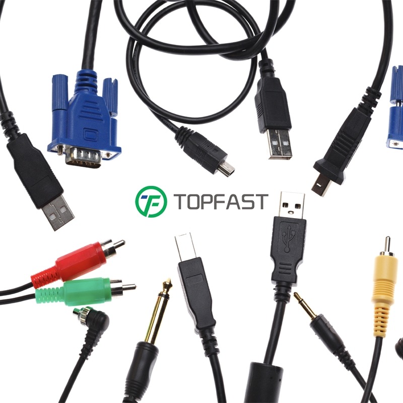
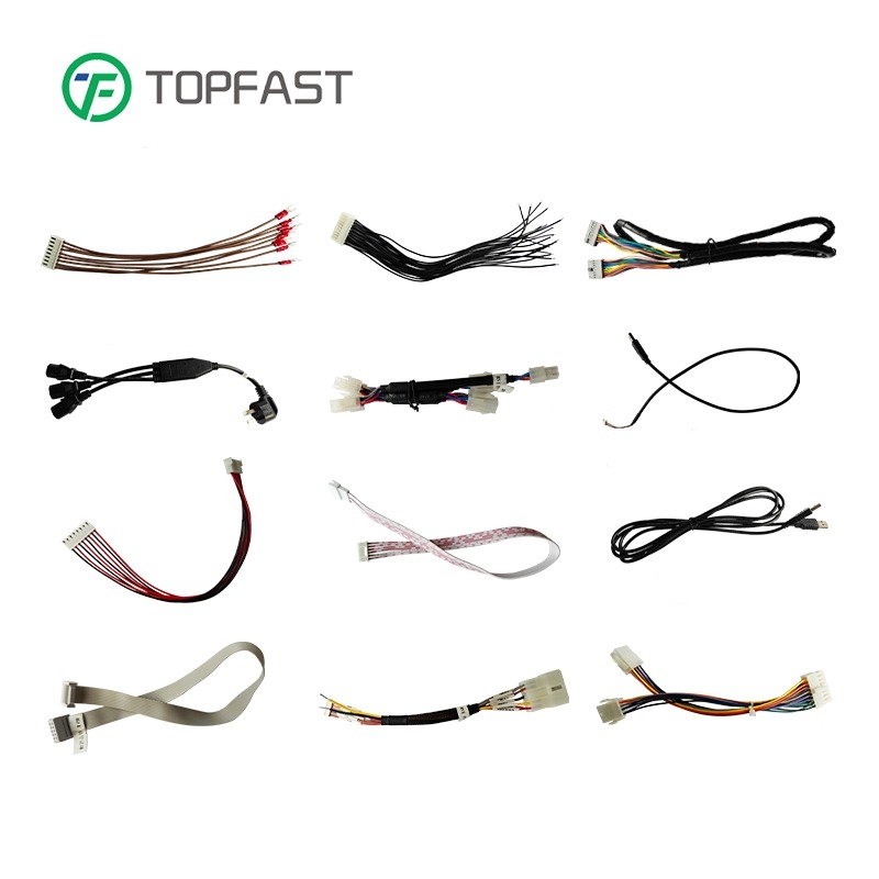
Wire harnesses, commonly referred to as cable assemblies, are integrated systems comprising multiple components such as conductors, wires, cables, and connectors. They connect and power complex electrical systems, serving as fundamental components in critical sectors including data centers, industrial machinery, aircraft, and medical equipment.
Even modern household appliances and electronics, despite their advanced nature, require diverse cables and connectors. Harnesses simplify these connections and facilitate cable management, yet this represents only the tip of the iceberg in terms of their functionality.
Carefully engineered harnesses minimize interference or loss, ensuring signal integrity. Since they must distribute power and signals to different components, preventing cross-interference is crucial. High-stress environments like factories require robust harnesses to ensure safety and meet industry standards, while subpar designs complicate maintenance and installation.
2. Basic Principles of Harness Design
1. Design Efficiency
Designers must first clarify the requirements of the harness, including environmental conditions as well as electrical parameters such as voltage, current, and signal requirements. Specifications are then compiled based on these attributes to guide the entire design process, thereby minimizing design complexity while maximizing functionality.
2. Reliability and Durability
Selecting appropriate materials based on specifications is crucial, including wire types, connectors, and terminals. Sharp bends and wear must be avoided, so designers must carefully plan cable routing paths. Harness design should incorporate stress relief devices, clamps, ties, and sleeves for support.
The automotive industry is a typical example of how harness design improvements have brought revolutionary changes. By simplifying designs and optimizing material selection, automotive manufacturers have successfully increased harness production and development efficiency.
3. Cost Effectiveness
Optimized design ensures that resources and materials used for manufacturing harnesses are utilized optimally, reducing waste and lowering overall costs. Excellent harness designers can tailor designs to specific use cases and needs, resulting in significant savings in power, chemicals, water, and human resources.
3. Comparison of Key Wire Harness Design Methods
| Design Method | Cost Level | Results and Characteristics |
|---|---|---|
| Standard Design | Low | Provides basic functionality but may have a higher failure risk and moderate maintenance costs |
| Enhanced Design | Medium | Offers higher reliability and lower maintenance costs |
| Premium Design | High | Provides optimal reliability, minimizes failure occurrence, and reduces maintenance costs |
| Custom Design | Varies based on custom needs | Offers a flexible design tailored to specific requirements, which may be the most expensive option |
4. Best Practices for Designing Efficient and Reliable Harnesses
1. Material Selection
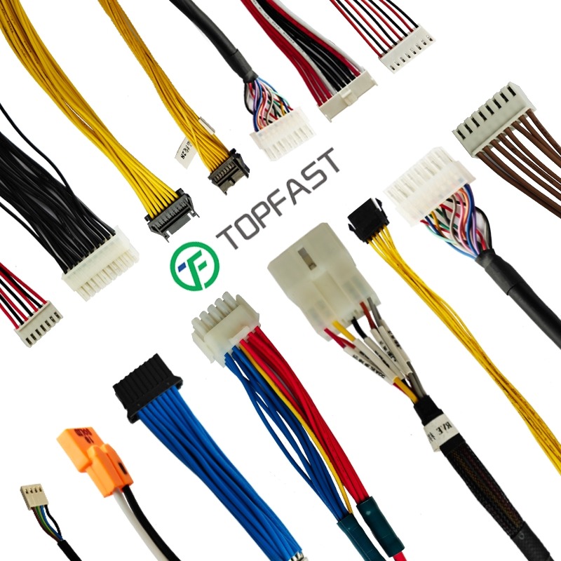
Wire harness materials are divided into three major categories: conductors (wires), insulating materials, and connectors. Materials should meet the specified current-carrying capacity, insulation performance, and operational environment requirements.
Wire Harness Material Selection Guide
| Category | Material | Description and Characteristics |
|---|---|---|
| Wires (Conductors) | Copper | Widely used conductor with excellent conductivity and flexibility |
| Aluminum | Lighter and cheaper alternative to copper | |
| Insulating Materials | PVC (Polyvinyl Chloride) | Flexible insulator with good dielectric properties |
| Polyethylene (PE) | Insulating material with excellent moisture and chemical resistance | |
| Teflon (PTFE) | Excellent thermal insulation and dielectric properties | |
| Thermoplastic Elastomer (TPE) | Utilizes rubber and plastic properties to provide flexible and durable insulation | |
| Connectors | Crimp Connectors | Provide secure and reliable connections, common in the industrial and automotive industries |
| Soldered Connectors | Suitable for high-demand applications requiring strong permanent connections | |
| Push-in Connectors | Enable tool-free connections, primarily used in consumer electronics | |
| Terminal Blocks | Provide stable, secure, and organized connections through multiple wires, common in industrial applications |
2. Cable Management
Harnesses must avoid damage caused by bundling, bending, and other structural obstacles. Main protection techniques include:
- Bundling Wires: Use cable ties and lacing cords to organize and secure wires
- Protective Sleeving and Conduits: Use braided sleeving to protect wires from abrasion and environmental factors
- Stress Relief: Add stress relief sleeves at connection points to protect wires from excessive pulling and bending
Before bundling, it is best to plan and define specific routing paths. Clamps and fixtures can be used to secure harnesses along routing paths.
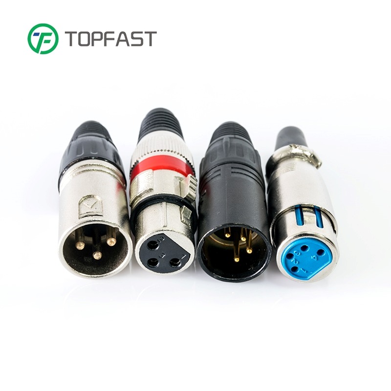
3. Connector Selection and Placement
Harness connectors must meet the voltage and current requirements of their application scenarios. Different connectors are compatible with different signal types. Other considerations include:
- Temperature range adaptability
- Moisture and dust resistance
- Vibration and shock resistance (caused by the operational environment)
Connector positioning should ensure easy assembly, maintenance, and troubleshooting. External and internal components or structures should not obstruct connectors, while avoiding placement near heat sources and ensuring necessary ventilation.
4. Shielding and Protection
Separate power and signal lines to prevent electromagnetic interference (EMI) and ensure signal integrity. Use EMI shielding technologies and materials for sensitive lines.
5. Documentation and Labeling
Each wire should be labeled, indicating its function and purpose, facilitating installation, troubleshooting, and maintenance. Colored labels or wires are recommended to indicate different functions or circuits.
Design documentation should include detailed schematics and diagrams illustrating the routing and connections of all wires within the cable assembly.
5. Core Contradictions and Solutions in Smart Equipment Harness Design
Modern smart equipment harnesses face the fundamental contradiction between functional integration and spatial limitations: they must undertake compound functions such as power transmission (e.g., 800V high voltage in new energy equipment), high-speed data exchange (5G/Ethernet signals), and environmental sensing (temperature/position sensors), while also meeting physical constraints such as lightweight requirements (aerospace demands weight reduction of over 30%) and high-density layout (medical equipment requires wire diameters less than 0.5mm).
Resolving this contradiction requires following the three core principles:
- Functional Integration Priority: Reduce physical cable count through protocol integration (e.g., Power over Ethernet technology)
- Spatial Topology Optimization: Use 3D simulation technology to pre-validate routing paths and avoid assembly interference
- Material Performance Breakthrough: Such as nano-coated wires that simultaneously achieve high conductivity and anti-electromagnetic interference
System-Level Solutions for Simplified Harness Design
(1) Modular Architecture Design
- Functional Decoupling: Separate power, signal, and control harnesses into independent modules with standardized interfaces for plug-and-play capability
- Layered Management: Reference “backbone-branch” structure, using high-bandwidth composite cables for backbone and customizing branch lines as needed
(2) Intelligent Predictive Maintenance System
- Embed micro-sensors at key nodes to monitor harness temperature, strain, and other parameters in real time
- Establish lifespan prediction models through digital twin technology to replace potential failure segments in advance
Key Technical Practices for Simplified Harness Design
(1) Routing Process Innovation
Use advanced technologies such as 3D printing, laser welding, and adaptive bending algorithms to solve harness layout challenges.
(2) Material and Structural Optimization
- Composite Material Applications: Copper-graphene hybrid wires (25% higher conductivity, 18% weight reduction)
- Self-Healing Insulation Layers: Microcapsule technology automatically forms protective films at damaged areas
- Space Folding Design: Snake-belly structure inspired by origami art enables harness expansion ratio of 1:5
6. Common Challenges in Harness Design and Solutions
Various factors can make harness design challenging, but these complexities can be managed and overcome through appropriate methods.
1. Managing Complexity
Designers must ensure all connections are properly routed, even in confined spaces, without affecting functionality. Modular design is one of the best methods to manage harness design complexity, dividing harnesses into smaller sections or sub-harnesses for easier connection and disassembly, simplifying maintenance and repair.
2. Ensuring Traceability and Quality Control
The ability to track harness history, location, and usage is crucial. Manufacturers should establish continuous feedback loops to collect information from customers and consumers, using this information to improve harness design.
Manufacturers must ensure necessary inspections and tests are performed, including:
- Electrical Tests: Insulation resistance tests, continuity, and voltage withstand tests to verify harness integrity
- Environmental Tests: Evaluate the harness’s ability to withstand environmental conditions
- Functional Tests: Test harnesses in intended applications to verify proper operation
Manufacturers must always consult the latest guidelines, regulations, and standards to ensure manufacturing processes and final products comply with requirements.
3. Balancing Cost and Performance
Using only the highest quality materials is unrealistic, as while high-quality materials can improve performance, they also increase costs. The best approach is to select materials that meet specified design attributes as much as possible and carefully choose suppliers when procuring materials.
7. Step-by-Step Guide to Wire Harness Design
Step 1: Requirements Gathering
Collect information to determine voltage, current, signal types, and other electrical specifications. Use spatial constraints, flexibility, and environmental conditions to determine mechanical requirements.
Step 2: Conceptual Design
Create wiring diagrams outlining connections between components to determine the basic structure of the harness. Select appropriate wires, connectors, terminals, and protective sleeves based on material requirements.
Step 3: Detailed Design and Layout
Use CAD software to draw the physical layout of the harness and its routing paths.
Step 4: Prototyping and Testing
Manufacture prototypes to validate designs. Prototypes should undergo electrical and environmental testing to ensure designs require no adjustments before full production.
Step 5: Final Design and Documentation
Finalize designs before manufacturing. Detailed documentation must be prepared, including assembly instructions, parts lists, and test procedures to guide the manufacturing process.
Manufacturers must implement strict quality control measures at each critical step of the manufacturing process to ensure final products are defect-free and meet strict design specifications.
8. Key Considerations in Harness Design
1. Application Purpose and Requirements
Beyond transmitting electrical signals and power in systems, specific application needs of harnesses must be considered: Is vibration resistance needed? EMI protection required? Must withstand high temperature or high-pressure environments?
2. Wire Selection Guidelines
- Wire Gauge: Select appropriate wire gauge based on current carrying capacity and current amount, considering voltage loss due to length
- Environmental Conditions: Choose wires suitable for the application environment, such as high temperature ratings or moisture-resistant coatings
- Mechanical Properties: Wires should withstand bending or twisting without damage or loss of electrical properties
3. Wire Connection Technology
Connector selection should be based on electrical and mechanical properties, considering wire material, gauge, and length. Also consider circuit size, density, and space constraints, as well as ease of connection and disconnection when necessary.
4. Routing Path Planning
Ensure wire routing allows for easy accessibility, with optimal positioning being key. Consider potential EMI sources and minimize interference risks. Isolate wires by function, voltage, and signal type to prevent interference.
5. Stress Relief Design
Identify potential stress sources and use components such as gaskets, cable clamps, or cable ties to protect harnesses. Stress relief components should be placed at the most vulnerable points in the harness, such as where wires exit the harness.
6. Harness Diagram Design
Use professional design tools to create detailed wiring diagrams, improving accuracy and design quality while ensuring compliance with industry standards and specifications. These tools can help identify potential issues such as inter-wire interference, voltage drop, or wire length limitations.
7. Protective Sleeving Selection
Select appropriate protective sleeving or conduit materials based on environmental conditions to provide additional insulation layer protection for wires and cables. Options range from pull-on braided sleeves to tapes, spiral wraps, and heat-shrink sleeves.
8. Testing and Validation
Consider testing strategies early in the design phase, using appropriate equipment to check electrical integrity and locate faults in all conductors. Tests should include resistance measurement, limit setting, and intermittent connection checking.
9. Complete Documentation
Documentation is crucial for after-sales service and technical personnel, including schematic designs and all connector information, as well as smart technical publication exports.
10. Compliance Requirements
Ensure harness designs comply with relevant regulations and standards, such as IPC/WHMA-A-620 (industry standard for harness assembly), and international standards such as IEC, CEE, and CENELEC (for international markets).
9. Future Development Directions
- Wireless Alternatives: Partial replacement of low-speed signal lines with 60GHz millimeter-wave communication
- Bio-Inspired Design: Mimic neural network fractal structures for self-organizing wiring
- Sustainable Materials: Develop recyclable and bio-based materials to reduce environmental impact
- Integrated Sensing: Integrate more sensing functions directly into harness structures
Frequently Asked Questions (FAQ)
What are the key principles of wire harness design?
Design efficiency, durability, reliability, and cost effectiveness are the main principles of wire harness design.
What materials are best for designing durable harnesses?
The best materials for harness design are copper (as a conductor) and PVC (as an insulating material), but specific choices should be based on application requirements.
What are common challenges in harness design? How to address them?
Challenges include complex design and material requirements, environmental factors, and documentation and traceability. Many such challenges can be overcome by following harness design best practices and adopting modular approaches.
How to balance cost and performance in harness design?
An optimal balance between cost and performance can be achieved by selecting materials that meet specified design attributes rather than simply choosing the most expensive materials and carefully selecting suppliers.
What are the most noteworthy new technologies in modern harness design?
3D simulation technology, predictive maintenance systems, composite materials (such as copper-graphene hybrid wires), and self-healing insulation layers are currently the most noteworthy technological development directions.