Table of Contents
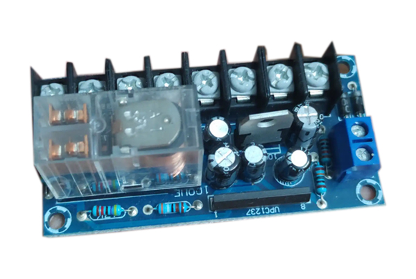
What is a PCB relay?
PCB relays (Printed Circuit Board Relays) are miniature relays that can be mounted directly onto a PCB to energize and de-energize circuits through control signals intelligently. Its core function is to safely control high-voltage circuits using low-power circuits while providing current isolation – a key advantage that transistorized switches cannot replace.
Core Advantages
1. Compact Integration
Designed for PCBs, it is small and lightweight, supports through-hole process installation, and is suitable for high-density circuit board layout.
2. Electrical Safety
Physical isolation (separation of contacts and coils) protects the low-voltage control side from high-voltage side interference, reducing system risk.
3. Flexible Adaptation
Various types (e.g. signal relays, power relays, solid state relays, etc.) are available to match different voltage/current requirements.
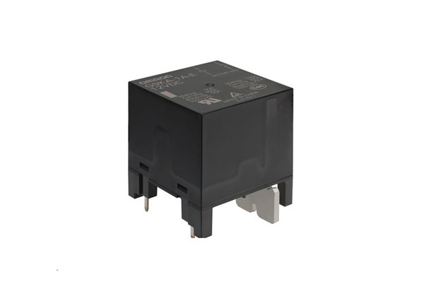
PCB Relay Characteristics
1. High voltage/current carrying capacity
Designed for high voltage (e.g. 220V AC/DC in industrial control) and high current (10A+) applications to ensure stable switching of power loads.
Typical applications: motor control, power distribution systems, electrical cabinet protection.
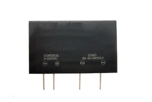
2. Semiconductor Technology (Solid State Relay/SSR)
Non-contact design: Electronic switching through semiconductors (e.g. MOSFETs, thyristors), no mechanical wear, and longer life.
Low interference: avoid sparks and electromagnetic noise of traditional relay contacts, suitable for precision electronic equipment.
Applicable scenarios: high-frequency switching (such as PLC signal control), explosion-proof environment.
3. Delay trigger function
Built-in time relay module, action delay can be set (e.g. 0.1s~10s) for timing control or preventing false triggering.
Example: motor soft start, equipment power failure buffer protection.
4. Temperature protection (thermal relay)
Integrated temperature sensor or bimetal to automatically disconnect the circuit when the ambient/load temperature exceeds the threshold value (e.g. 85°C).
Protection objects: power modules, transformers, high-power semiconductor devices.
5. Frequency protection (AC system specific)
Monitors AC frequency (e.g. 50/60Hz) and triggers tripping when abnormal (±5% offset) to prevent equipment damage.
Typical applications: generator grid-connected protection, inverter output monitoring.
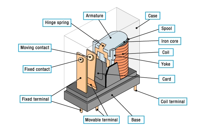
Core Structure Composition
PCB relays are mainly composed of the following key components:
Electromagnetic coil: the core component that generates a magnetic field when energized.
Armature (armature): movable iron piece driven by the magnetic field, which directly controls the opening and closing of contacts.
Contacts: including normally open (NO), normally closed (NC), and common (COM), used to energize and break the circuit.
Spring/Reset Mechanism: Returns the armature to the initial state of the contacts when power is lost.
Yoke: A magnetically conductive frame that concentrates the magnetic field to increase
How does a PCB relay work?
1. Excitation Stage
When the control circuit applies a rated voltage (e.g. 5V DC/24V DC) to the coil, current passes through the coil.
The coil generates an electromagnetic field that magnetizes the yoke and attracts the armature towards the core.
2. Contact action
The armature drives the contact mechanism:
Normally closed contact (NC): breaks the connection.
Normally open contact (NO): closed connection.
At this point, the load circuit is connected or cut off (depending on the contact configuration).
3. Reset stage
When the coil is de-energized, the magnetic field disappears and the spring force pushes the armature to reset.
The contacts return to their initial state (NC closed, NO disconnected).
Relay PCB Types
The “Pole” and “Throw” of a relay are key parameters describing its contact configuration, which directly affects the circuit control capability. The following are common types and characteristics of PCB relays:
1. Single Pole Single Throw (SPST, Single Pole Single Throw)
Structure: 1 set of contacts, only 1 conduction position (normally open or normally closed).
Function: The simplest form of switching, only a single circuit can be energized.
Symbol:
┌───────┐
│ ○───┤ (Normally open type)
└───────┘
Typical applications: power switching, LED control, and other basic on/off scenarios.
2. Single Pole Double Throw (SPDT, Single Pole Double Throw)
Structure: 1 set of contacts, 2 conduction positions (normally open + normally closed + common terminal).
Function: The common terminal (COM) can be switched to two independent circuits, realizing two selective controls.
Symbol:
┌───────┐
│ ○───┤ (COM→NO)
│ ○───┤ (COM→NC)
└───────┘
Characteristics:
Two states: default closed (NC) or default disconnected (NO).
A brief disconnection exists when switching (Break-before-make).
Applications: signal switching, motor forward and reverse control.
3. Double Pole Single Throw (DPST, Double Pole Single Throw)
Structure: 2 groups of independent contacts, each group of 1 conduction position (equivalent to two SPST parallel).
Function: Synchronized control of two circuits, but each group of contacts only on and off once.
Symbol:
┌───────┐
│ ○───┤ (Contact 1)
│ ○───┤ (Contact 2)
└───────┘
Application: Simultaneous cut-off of fire/zero line (e.g. safety switch), dual power control.
4. Double Pole Double Throw (DPDT, Double Pole Double Throw)
Structure: 2 groups of contacts, each group of 2 conduction positions (equivalent to two SPDT in parallel).
Function: Independent switching of two bi-directional circuits to support complex control logic.
Symbol:
┌───────┐
│ ○───┤ (COM1→NO1)
│ ○───┤ (COM1→NC1)
│ ○───┤ (COM2→NO2)
│ ○───┤ (COM2→NC2)
└───────┘
Features:
Can control two loads in forward/reverse direction at the same time (e.g. DC motor H-bridge drive).
Applications: industrial automation, robot joint control.
Basic Design Requirements for PCB Relays
To ensure the reliability and long-term stability of relays on PCBs, the design must consider material selection, layout optimization, process specifications, and environmental protection. Below are the core design principles:
1. PCB Material and Thickness
- Substrate Thickness:
- Recommended: 1.6mm (standard for through-hole mounting) to ensure mechanical strength and minimize soldering deformation.
- For high-frequency/high-density applications, 0.8–1.0mm may be used (evaluate bending resistance).
- Substrate Type:
- FR-4 Glass Epoxy: General-purpose, heat-resistant (Tg ≥ 130°C), cost-effective.
- CEM-1/Paper Epoxy: Low-cost, suitable for low-power applications.
2. Conductor (Copper Foil) Thickness
- Standard Options:
- 35μm (1oz): Low-current signal traces (<2A).
- 70μm (2oz): High-current load paths (e.g., contact circuits, ≥5A) to reduce temperature rise.
- Special Requirements: For high-current relays (>10A), consider localized copper thickening (e.g., 105μm).
3. Layout and Spacing Specifications
- Electromagnetic Interference (EMI) Protection:
- Keep relay coils at least 5mm away from sensitive components (e.g., MCUs, ADC chips).
- Maintain ≥2.5mm spacing between high-voltage contacts and low-voltage control traces (250V AC).
- Thermal Management:
- Avoid placement near heat-generating components (e.g., power ICs, transformers) or add thermal vias.
- For high-temperature environments (>85°C), use heat-resistant relays (e.g., OMRON G5V series).
4. Mounting and Mechanical Protection
- Soldering Process:
- Through-hole relays: Wave or hand soldering, ensuring full solder joints without voids.
- SMT relays: Reflow soldering temperature profile must match relay specifications (typically ≤260°C).
- Vibration Resistance:
- Orient relays so that vibration/shock forces are perpendicular to the armature movement (reduces false triggering).
- For high-vibration environments (e.g., automotive), use relays with shock-absorbing adhesive or reinforced springs.
5. Cleaning and Protection
- Post-Soldering Cleaning:
- Use no-clean solder paste or isopropyl alcohol to remove flux residues, preventing contact corrosion.
- Conformal Coating:
- Apply protective coating (e.g., polyurethane) in humid/contaminated environments to cover relay pins and PCB traces.
Design Pitfalls and Common Mistakes
- Mistake 1: Running high-voltage contacts parallel to signal traces → causes crosstalk.
Solution: Use orthogonal routing or add isolation slots. - Mistake 2: Insufficient coil drive current → incomplete contact engagement.
Solution: Ensure the drive circuit provides rated voltage/current (e.g., 5V/20mA).
Relay Selection Reference Table
| Parameter | Recommended Value/Method | Notes |
|---|---|---|
| PCB Thickness | 1.6mm (through-hole) | Increase to 2.0mm for high vibration |
| Copper Thickness | ≥70μm for contacts, 35μm for coil | Thicken high-current paths |
| Coil-Contact Spacing | ≥5mm (low voltage) or per rating | ≥2.5mm for 250V AC |
| Soldering Temp | ≤260°C (SMT) | Verify the relay datasheet |
PCB Relay Mounting Techniques
I. Soldering Process Specifications
- Soldering Methods
- Manual Soldering:
- Use a 30- 60W soldering iron with a clean tip.
- Maintain tip temperature at 350°C max to prevent thermal damage.
- Solder each pin for ≤3 seconds to avoid overheating.
- Automated Soldering:
- Wave Soldering:
- Adjust solder wave height to prevent overflow onto the PCB.
- Standard profile: 260°C (±5°C) for 6 seconds.
- Reflow Soldering (SMT):
- Follow relay-specific temperature curves (typically peak ≤260°C).
- Critical Notes
- Multilayer PCBs: Higher thermal mass may require extended preheating to ensure proper solder joint formation.
- Flux Application: Use no-clean flux to minimize post-soldering residues.
II. Installation & Electrical Connection
- Mounting Types
- Through-Hole (THT):
- Pins are inserted into drilled holes, soldered on the opposite side.
- Provides strong mechanical bonding for high-vibration environments.
- Surface Mount (SMT):
- Reflow-soldered directly onto pads; ideal for compact designs.
- Wiring Guidelines
- Coil Terminals: Connect to control signals (e.g., MCU GPIO) with current-limiting resistors if needed.
- Contact Terminals:
- NO/NC/COM pins wired in series with load circuits (motors, lamps).
- Ensure trace width supports load current (e.g., 70μm Cu for 5A+).
- Isolation Requirements
- Maintain ≥2.5mm creepage distance between coil and high-voltage contacts (250V AC).
- Verify dielectric strength (1kV+ isolation) between control and load circuits.
III. Post-Installation Steps
- Cooling & Cleaning
- Allow PCB to cool naturally; avoid forced cooling to prevent thermal stress.
- Clean flux residues with isopropyl alcohol (IPA) if non-no-clean flux is used.
- Inspection & Testing
- Visual Check: Verify solder joints are shiny, concave, and free of bridges/cracks.
- Continuity Test: Use a multimeter to confirm:
- Coil resistance matches datasheet values.
- Contact continuity (NO/NC states) switches correctly when energized.
IV. Common Pitfalls & Solutions
| Issue | Cause | Solution |
|---|---|---|
| Solder Bridging | Excessive solder or misalignment | Adjust stencil thickness/reflow profile |
| Overheated Relay | Prolonged soldering time | Strictly limit soldering to ≤3s per pin |
| Intermittent Contact | Poor solder joint or contamination | Reflow/rework with fresh flux |
Testing PCB Relays
When a relay is not energized, NO and NC remain open and closed, respectively. A multimeter is required to test the relay. After that, you can refer to the following steps to test the PCB relay:
- You need to set the multimeter to continuity check mode.
- You need to test the continuity between the NC contacts and the poles.
- You have to check the discontinuity between the normally open contacts and the poles.
- Next, energize the relay to energize the coil. This will make a clicking sound. This is because the contacts are now switching from the Normally Closed (NC) to the Normally Open (NO) position in response to the magnetic field.
- You will need to check for continuity between the normally open contacts and the poles.
- Test for discontinuity between the NC contact and the pole.
- Finally, measure the resistance of the coil with a multimeter. Check that it matches the resistance labeled on the manufacturer’s relay.
PCB relays can be used as a protection system for an entire circuit system. Although small in size, they are effective in protecting the entire system from damage and operate on the same principle as standard-size relays.PCB design requires full consideration of all aspects of PCB relays.
If you need help? Contact us at op@topfastpcb.com
Need a PCB or PCBA Quote? Get a quote now!
Related reading
1.Songle Spdt Miniature PCB Mount Relay
2.12v Spdt Super Miniature PCB Mount Relay
3.Songle Spdt 5 Pin Miniature PCB Mount Relay
4.5 Pin Relay
5.30 Amp Relay
6.Voltage Sensing Relay