Table of Contents
What does an automotive PCB board mean
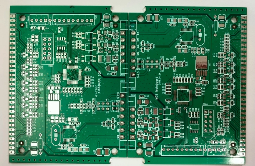
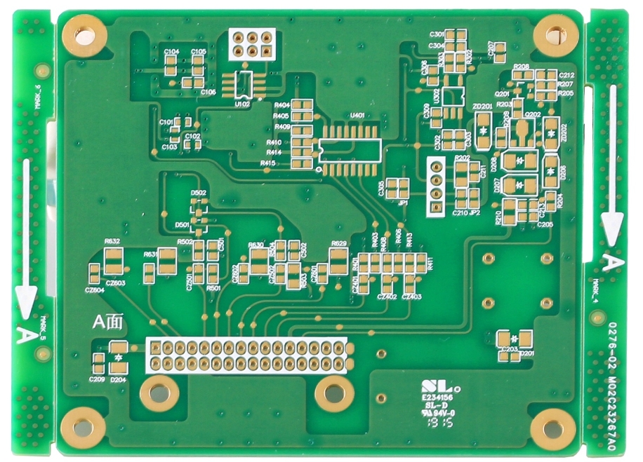
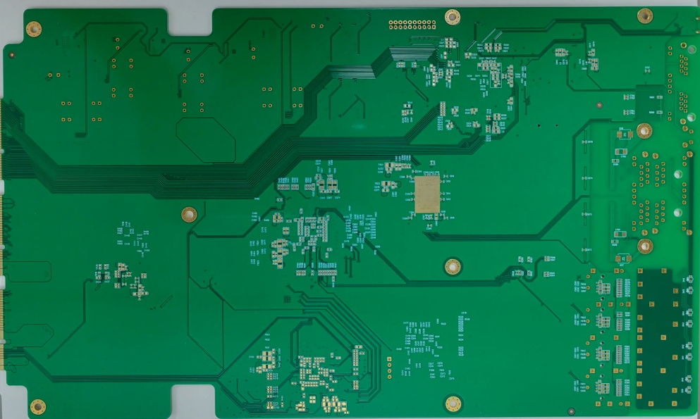
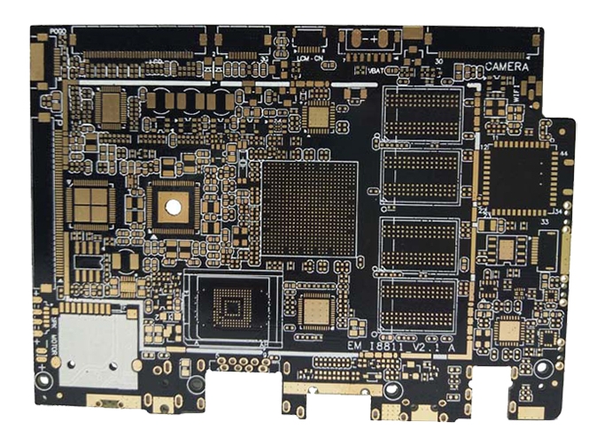
Automotive PCB (Printed Circuit Board) refers to printed circuit boards designed and manufactured for automotive electronic systems. The core component of modern automotive electronics consists of conductive materials (such as copper foil) and insulating substrates (e.g., FR-4) fabricated through precision printing processes to enable electrical interconnections and mechanical support for electronic components.
Key Features:
- High-Reliability Design
- Wide operating temperature range (-40°C to 125°C)
- Vibration-resistant, moisture-proof, and chemical corrosion-resistant
- Higher mean time between failures (MTBF) requirements
- Stringent Quality Standards
- Must comply with automotive industry certifications (e.g., AEC-Q100)
- Adherence to ISO/TS 16949 quality management systems
- Use of automotive-grade materials and specialized manufacturing processes
Main Types & Applications:
- Rigid PCBs
- Applications: Engine Control Units (ECUs), transmission control systems
- Features: High mechanical strength, suitable for high-vibration environments
- Flexible PCBs (FPCs)
- Applications: In-vehicle displays, sensor wiring
- Features: Bendable, adaptable to tight installation spaces
- Applications: Automotive cameras, ADAS systems
- Features: Combines the advantages of rigid and flexible PCBs
Technology Trends:
- High-Density Interconnect (HDI) Technology
- Supports the miniaturization of automotive electronics
- Enhances signal transmission quality
- High-Power Design
- Adapts to high-voltage systems in electric vehicles (e.g., BMS)
- Improved thermal management
- Smart Integration
- Supports vehicle-to-everything (V2X) communication
- Compatibility with autonomous driving systems
With the continuous advancement of automotive electronics, the proportion of PCBs in vehicles is steadily increasing. It is estimated that by 2025, the average PCB value per vehicle will rise to approximately $80–120, with an even higher share in electric vehicles.
Key Manufacturing Processes of Automotive PCBs
The production of automotive printed circuit boards (PCBs) involves a series of precise manufacturing steps, collectively ensuring high reliability and long-term stability in harsh automotive environments. Below is a detailed breakdown of the core processes:
1. Material Selection & Substrate Preparation
- Base Material: High-performance substrates such as high-Tg FR-4 (Tg ≥170°C), Rogers high-frequency materials, or aluminum-based boards are prioritized.
- Surface Finish: Processes like ENIG (Electroless Nickel Immersion Gold, Ni thickness 3-5μm), OSP (Organic Solderability Preservative), or immersion tin are selected based on application requirements.
- Special Requirements: All materials must comply with UL certification and AEC-Q100 reliability validation.
2. Inner Layer Circuit Fabrication
- Pattern Transfer: LDI (Laser Direct Imaging) technology achieves ≤50μm circuit precision.
- Etching Control: Line width/spacing tolerance maintained within ±15%, impedance matching error ≤±7%.
- Surface Treatment: Black oxide/browning processes ensure copper surface roughness (Ra) between 0.3-0.8μm.
3. Multilayer Lamination Process
- Layer Alignment: CCD vision alignment systems ensure interlayer misalignment ≤25μm.
- Lamination Parameters: Vacuum hot pressing at 180-200°C, 300-400psi pressure, with a heating rate of 2-3°C/min.
- Quality Control: Ultrasonic testing detects interlayer bonding integrity, eliminating delamination risks.
4. Precision Drilling Technology
- Drilling Process: Tungsten carbide drill bits (0.15-0.3mm diameter) with stack thickness ≤1.2mm.
- Hole Wall Quality: Roughness ≤25μm, nail-head effect controlled within 10%.
- Metallization: Electroless copper plating + electroplating ensures hole wall copper thickness ≥25μm.
5. Reliability Enhancement Testing
- Environmental Testing:
- Thermal shock testing: -40°C ↔ 125°C, 500 cycles.
- Vibration testing: 20-2000Hz random vibration, ≥96 hours duration.
- Mechanical Testing:
- Peel strength ≥1.0N/mm.
- Flex endurance ≥100 cycles (for flexible PCBs).
6. Full-Process Quality Control
| Inspection Item | Method | Control Standard |
|---|---|---|
| Circuit Defects | AOI (Full Inspection) | Resolution ≤3μm |
| Impedance Control | TDR Testing | Deviation ±7% |
| Ionic Contamination | Dynamic Extraction | NaCl Equivalent ≤1.5μg/cm² |
| Thermal Reliability | IST Testing | ≥1000 Cycles |
| Special Process Requirements: |
- High-voltage PCBs require copper thickness ≥70μm.
- High-frequency circuits demand dielectric constant (Dk) tolerance within ±0.05.
- PCBs for autonomous driving must ensure signal integrity (SI) loss ≤0.5dB/inch.
Automotive PCB manufacturing standards far exceed those of consumer electronics, with over 120 in-process inspection checkpoints to guarantee stable performance throughout the product lifecycle (typically 15 years). As automotive electronics evolve, demand for advanced processes like embedded resistors/capacitors and any-layer interconnects continues to grow.

The whole process of automotive electronics PCBA processing
Raw Material Preparation Stage
- Substrate Selection Standards:
- High Tg (≥170℃) FR-4 substrates or polyimide flexible substrates
- Compliance with UL94 V-0 flame retardant rating and IPC-6012DA standards
- Typical thickness: 0.8-2.4mm (up to 16 layers for multilayer boards)
- Component Quality Control:
- AEC-Q100/200 certified components
- Operating temperature range: -40℃~150℃ (for engine compartment applications)
- Incoming inspection items:
- Visual inspection (20x microscope)
- Electrical parameter testing (LCR meter)
- Solderability test (245℃±5℃)
SMT Precision Assembly Process
- Solder Paste Printing Control:
- Stencil parameters:
- Thickness: 0.1-0.15mm
- Aperture accuracy: ±15μm
- Tension requirement: ≥35N/cm²
- Printing parameters:
- Squeegee pressure: 5-10kg
- Printing speed: 20-50mm/s
- Separation speed: 0.5-2mm/s
- High-Precision Placement Technology:
- Placement machine accuracy: ±25μm@3σ
- 0201 component placement yield: ≥99.95%
- BGA chip alignment accuracy: ±15μm
- Reflow Soldering Process:
- Typical temperature profile:
- Preheat zone: 1.5-3℃/s (150-180℃)
- Reflow zone: 230-245℃ (60-90s)
- Cooling rate: <4℃/s
- Oxygen content control: <1000ppm
THT Insertion Process (for applicable models)
- Insertion Requirements:
- Lead forming accuracy: ±0.1mm
- Insertion depth: board thickness +1.5mm
- Polarity component anti-misinsertion measures
- Wave Soldering Key Parameters:
- Solder temperature: 250±5℃
- Wave height: 0.8-1.2mm
- Conveyor speed: 1.2-1.8m/min
- Flux spray volume: 3-5g/m²
Comprehensive Inspection System
- Inspection Project Matrix:
| Inspection Stage | Method | Equipment | Standard |
|---|---|---|---|
| Incoming Inspection | X-ray Inspection | X-ray Machine | IPC-A-610G |
| Post-Soldering Inspection | AOI Inspection | 3D AOI | Defect detection rate ≥99.9% |
| Functional Test | Boundary Scan | ICT Tester | Coverage ≥95% |
| Environmental Test | Thermal Cycling | Environmental Chamber | -40~125℃,500 cycles |
- Special Test Requirements:
- Infotainment systems: THD+N<0.1%
- Airbag controllers: Response time<10ms
- New energy BMS: Voltage sampling error<±5mV
Conformal Coating Process
- Coating Technical Parameters:
- Coating thickness: 25-75μm
- Curing condition: 80℃/30min
- Insulation resistance: ≥10¹²Ω
- Salt spray test: 96h without corrosion
- Typical Application Scenarios:
- Chassis electronics: Vibration+moisture protection
- On-board chargers: Triple insulation treatment
- ADAS systems: Nano coating protection
Quality Control Points
- Process Control Indicators:
- First-pass yield: ≥99.5%
- Solder joint yield: ≥99.99%
- ESD protection: <100V
- Traceability System:
- Batch traceability code: 20-digit unique identifier
- Process parameter storage: 10-year retention
- Failure analysis: 8D report closure
This process strictly complies with IATF16949 system requirements, with all processes establishing process capability indices of CPK≥1.33. For high-end products like autonomous driving domain controllers, additional signal integrity testing (eye diagram test) and EMC testing (radiated emissions <30dBμV/m) are required.

Automotive PCB Process Standards and Technical Specifications
Automotive electronic PCB designs must comply with a series of stringent international standards and technical requirements to ensure safe and reliable long-term operation under complex and variable environmental conditions. Below are the key process standards for automotive PCBs:
Environmental Adaptability Standards
- Temperature Resistance
- Operating temperature range: -40°C to 125°C (engine compartment components must withstand 150°C peak temperatures)
- Preferred materials: High-Tg laminates (Tg ≥ 170°C) such as Isola 370HR or Panasonic Megtron 6
- Critical components should use ceramic substrates or metal-core PCBs for enhanced thermal dissipation
- Humidity & Chemical Resistance
- Must withstand 85°C/85% RH damp heat testing for 1000+ hours
- Resistant to automotive fluids (coolant, fuel, brake fluid)
Reliability & Certification Requirements
- Durability Standards
- Design lifespan: 15 years or 200,000 km
- Mandatory compliance with:
- AEC-Q100 (ICs)
- AEC-Q101 (discrete semiconductors)
- AEC-Q200 (passive components)
- Testing & Validation
- Thermal cycling (-40°C to 125°C, 1000 cycles)
- Mechanical vibration (50Hz–2000Hz, 3-axis, 6-direction)
- High-temperature storage (150°C, 1000 hours)
EMC & Signal Integrity Design
- Layout & Shielding
- Strict functional zoning:
- Power domain (>100MHz)
- Safety domain (>100MHz)
- Infotainment domain (>1GHz)
- Faraday cage shielding for sensitive circuits (e.g., ADAS sensors)
- Routing Standards
- Impedance control: ±10% tolerance (±7% for high-speed signals)
- High-voltage spacing: ≥0.5mm/kV (for >60V circuits)
- Guarding traces: Critical signals must be ground-shielded (spacing ≤3x trace width)
Manufacturing & Process Control
- Dimensional Stability
- Z-axis CTE ≤ 3.0% (50–260°C)
- Laser Direct Imaging (LDI) for precision (±25µm alignment)
- Surface Finishes
- Preferred: ENIG (Electroless Nickel Immersion Gold) or OSP + selective gold plating
- High-voltage connectors: Hard gold plating (≥1µm)
Special Application Requirements
- Powertrain PCBs
- Must meet ISO 26262 ASIL-D functional safety
- 3oz heavy copper (current capacity ≥40A/cm²)
- Autonomous Driving Systems
- Low-loss materials: Dk ≤ 3.5, Df ≤ 0.005 @ high frequency
- Millimeter-wave PCBs: Df ≤ 0.002 @ 77GHz
This specification aligns with IPC-6012DA (Automotive PCB Qualification & Performance) and IATF 16949 quality management standards. It applies to all automotive electronic PCB designs and manufacturing processes. Standards will be periodically updated to reflect advancements in automotive electronics technology.
Automotive PCB Control Requirements Standard
Design Control Requirements
- Mechanical Design
- Strict compliance with vehicle installation space constraints (±0.15mm tolerance)
- 3D modeling for assembly simulation verification
- Vibration-resistant design for engine compartments (meets ISO 16750-3)
- Electrical Design Specifications
- Signal Integrity (SI) and Power Integrity (PI) co-design
- Tight impedance control for high-speed signals (±7% tolerance)
- Critical signals routed as differential pairs (3W spacing rule)
- Environmental Adaptability
- Material selection per IEC 60068-2 environmental test standards
- Multilayer boards require Z-axis CTE matching (≤3.5%)
- Moisture-proof coating (≥25μm) for high-humidity areas
Performance Control Requirements
- Electrical Performance
- Insertion loss: ≤0.3dB/inch@1GHz
- Crosstalk suppression: ≥60dB@100MHz
- Insulation resistance: ≥100MΩ (DC500V)
- Reliability Requirements
- Thermal cycling: -40°C~125°C, 1000 cycles (zero failures)
- Mechanical shock: 50g peak acceleration, 6ms duration, 3 axes ×1000
- Damp heat aging: 85°C/85%RH, 1000hrs (≤10% IR degradation)
- Durability Standards
- Design lifespan: ≥15 years/250,000km
- Failure rate: ≤10ppm/year (≤1ppm for safety-critical components)
Manufacturing Process Control
- Process Accuracy
- Trace width tolerance: ±10% (±7% for impedance lines)
- Layer-to-layer alignment: ≤25μm (LDI process)
- Hole position accuracy: ±50μm (mechanical drilling)
- Material Control
- UL-certified substrates meeting IPC-4101E
- Copper foil roughness: ≤1.5μm (≤0.8μm for RF applications)
- Prepreg flow: 35±5%
- Quality Inspection
- 100% AOI (≥99.9% defect detection)
- Flying probe testing for critical layers (100% coverage)
- IPC-A-600G Class 3 acceptance criteria
- Special Process Requirements
- High-voltage circuits: Increased creepage (≥0.5mm/kV)
- High-current traces: ≥2oz copper
- RF circuits: Low-loss materials (Df≤0.005)
Compliance Standards: - IPC-6012DA (Automotive PCB Qualification)
- IATF 16949 (Automotive QMS)
- AEC-Q100/200 (Automotive Component Reliability)
- ISO 26262 (Functional Safety)
Note: Safety-critical systems (ASIL-rated) require enhanced control parameters. Full traceability must be maintained throughout the production lifecycle.

Comparative Analysis: Automotive PCBs vs. Conventional PCBs
Material Properties Comparison
| Parameter | Conventional PCB | Automotive PCB |
|---|---|---|
| Base Material | Standard FR-4 (Tg 130-140°C) | High-Tg FR-4 (Tg≥170°C) or Polyimide |
| Copper Foil | Standard ED copper (1oz) | Low-profile foil (≤1.2μm RA) |
| Solder Mask | Standard liquid ink | High-reliability solid ink (UL-certified) |
| Special Reqs. | – | Chemical-resistant coating (≥25μm) |
Process Standards
- Manufacturing Precision
- Conventional: ±20% trace width, ±75μm hole tolerance
- Automotive: ±10% trace width (±7% impedance), ±25μm laser drilling
- Reliability Processes
- Conventional: Standard finishes (HASL/OSP)
- Automotive:
- ENIG (Ni≥5μm)
- Selective hard gold plating
- 100% microsection inspection
- Special Treatments
- Automotive PCBs require:
- Ionic contamination test (≤1.56μg/cm² NaCl eq.)
- Thermal stress test (288℃ solder float, 3 cycles)
Environmental Robustness
- Temperature Range
- Conventional: 0℃~70℃ (commercial)
- Automotive: -40℃~125℃ (150℃ peak in engine bay)
- Vibration Testing
- Conventional: Not required
- Automotive: ISO 16750-3 compliant (20-2000Hz sweep)
- Humidity Resistance
- Conventional: 85℃/85%RH/168hrs
- Automotive: 85℃/85%RH/1000hrs + thermal shock
Reliability Benchmarks
| Test Item | Conventional Standard | Automotive Standard |
|---|---|---|
| Thermal Cycling | -10℃~65℃, 200 cycles | -40℃~125℃, 1000 cycles |
| Mechanical Shock | Not required | 50G/6ms, 3 axes |
| Insulation Res. | ≥10MΩ | ≥100MΩ (500VDC) |
| Service Life | 3-5 years | 15 years/250,000km |
Certification Requirements
- Conventional PCBs
- Basic: UL94V-0, IPC-A-600 Class 2
- Automotive PCBs
- Mandatory:
- AEC-Q100/200 qualification
- IATF 16949 compliance
- IPC-6012DA standard
- ISO 26262 functional safety (ASIL rated)
Application Scenarios
- Conventional PCB Uses
- Consumer electronics
- Home appliances
- General industrial controls
- Automotive PCB Applications
- Powertrain: ECU, BMS
- Safety Systems: ABS, airbag control
- ADAS: mmWave radar, camera modules
- In-vehicle networks: CAN FD, Ethernet gateways
Technology Trends
- Automotive PCBs evolving toward HDI (≤50/50μm L/S)
- Emerging needs: Ultra-low loss materials for 77GHz radar (Df≤0.002)
- Smart inspection: AOI+AI defect recognition (≥99.95% accuracy)
Note: This comparison reflects industry standards. Actual parameters should be application-specific. Automotive suppliers must maintain complete PPAP documentation.
Founded in 2008, Topfast is a leading manufacturer of circuit boards with 17 years of experience in design, manufacturing, and assembly. It is a one-stop PCB solution provider specializing in rapid prototyping and low-volume manufacturing for customers. The company employs over 1000 people.
Our products include HDI boards, thick copper boards, backplanes, semiconductor test boards, high frequency boards, high speed boards, hard and soft combination boards, etc., to meet the various needs of customers. Our products are widely used in communication, medical equipment, industrial control, power supply, consumer electronics, aerospace, automotive industry, and other fields. All of our products are IPC rated and have passed UL, ROHS, and ISO9001 certifications.
