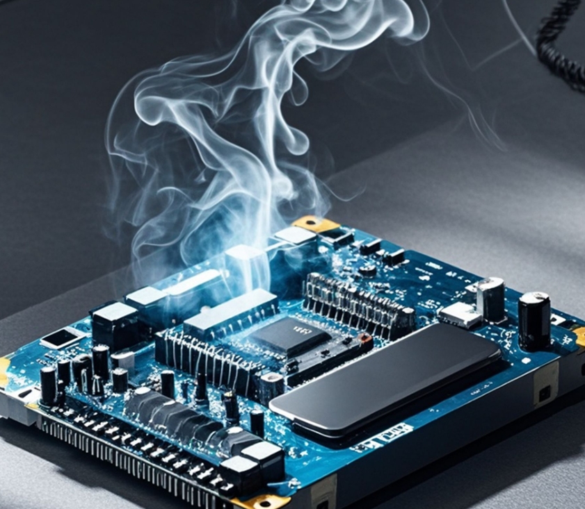
If you are producing a variety of PCBs (Printed Circuit Boards), the ability of the board to dissipate heat is critical. Effective heat dissipation prevents PCBs from overheating, causing performance problems or catastrophic failures. Choosing a PCB with proper thermal components prevents overheating and ensures reliable performance. Ensure the smooth operation of various components on the PCB board at a later stage and enhance the service life of the components.
Table of Contents
Factors affecting PCB heat dissipation
During the operation of electronic components, the flow of current leads to an increase in the heat load, and although the PCB can withstand a certain degree of heat, excessive temperatures may cause serious problems. Factors affecting the degree of heat generated by electronic components include circuit layout, power input and device characteristics. Improper component installation, external environmental factors, inadequate ventilation and incorrect assembly methods are all common causes of PCB overheating. For example, high temperatures can lead to broken circuit traces, component oxidation, compromised structural integrity, and mismatched material expansion coefficients.
Heat Dissipation Techniques in the PCB Industry
Considering the adverse effects of high temperatures, it is necessary to ensure that PCBs can dissipate heat. The following methods can effectively help PCB heat dissipation:
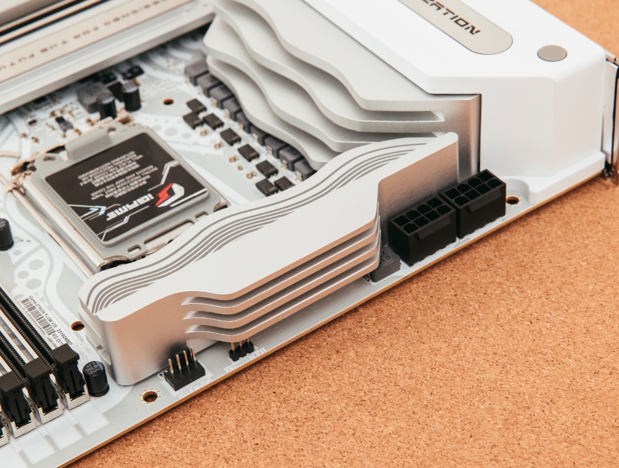
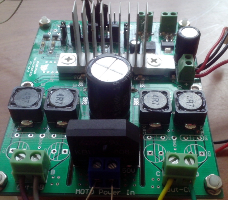
- Cooling Fans and Heat Sinks
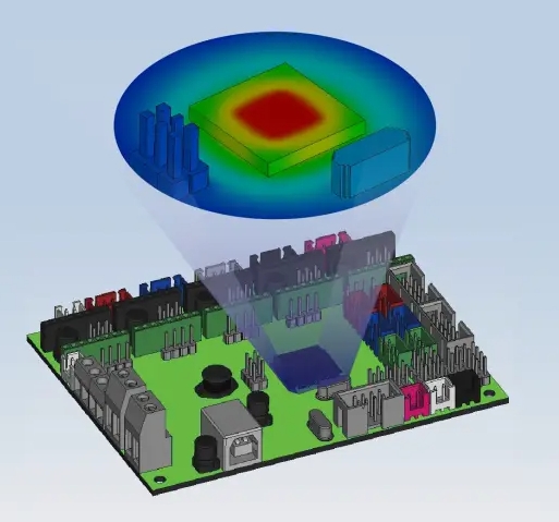
A heat sink is a metal component with high thermal conductivity and a large surface area, which is commonly used by PCB designers to improve heat dissipation. Heatsinks are usually mounted on heat-generating components (such as switching devices) so that heat is dissipated through the large surface area of the heatsink.
In addition to installing heat sinks in PCBs and other device components, cooling fans can also be used. Fans can introduce cool air to accelerate heat removal and prevent heat buildup. Often, high-current power supply devices use cooling fans to improve heat dissipation efficiency. - Thicker Copper Leads
In high current applications, thicker copper leads or tracks are recommended. Wider copper conductors provide a larger surface area, which helps heat spread and improves thermal efficiency. - Using Heat Pipes
Heat pipes are an effective heat dissipation solution in compact applications where space is limited. Heat pipes typically use a small amount of a liquid such as acetone, water, ammonia or nitrogen to absorb heat. The liquid absorbs heat, evaporates and flows through the tube, then cools and condenses back to liquid form in a condenser, creating a cycle of heat dissipation.
Heat pipes are widely used in passive heat dissipation systems because of their superior heat transfer capability, low cost and low maintenance requirements. In addition, heat pipes have no moving parts and do not generate noise and vibration. - Choosing the right board material
Using PCB materials suitable for heat dissipation is another way to improve heat dissipation. Some PCB materials cannot effectively withstand high temperatures, so in high-temperature environments, materials with excellent heat dissipation properties should be selected, such as a polyimide (Polyimide) substrate. - Thermal Management Solutions
-Flexible PCB (Flex PCB) Due to the thinness and good flexibility of the material, the surface area to volume ratio is greater, enabling more effective heat dissipation.
-Aluminum PCB (Aluminum PCB) is a metal core PCB with a dielectric layer that absorbs heat and conducts it to the aluminum layer, where it is dissipated. Aluminum PCBs are suitable for high-power devices.
-Copper PCBs have the best thermal conductivity and are suitable for high-energy tasks.
-Ceramic PCB (Ceramic PCB) Made of materials such as alumina or aluminum nitride, it has high thermal conductivity, low coefficient of thermal expansion, and excellent corrosion resistance, and is suitable for high-temperature and high-frequency applications. - Use of Thermal Overvia Arrays
Thermal via arrays reduce thermal resistance and improve thermal conductivity by increasing the area and mass of copper. For components that generate serious heat, thermal vias can be arranged near them to enhance the heat dissipation effect.
Thermal via arrays are a viable alternative if one wishes to minimize additional heat sinks on the PCB. In some applications, thermal vias can also be used in conjunction with pads to allow rapid heat transfer from the component to the heat sink unit. - Using Copper Coin Technology
Copper coins are small pieces of copper embedded in the PCB, usually placed underneath high heat components to take advantage of copper’s high thermal conductivity and allow heat to be transferred quickly to the heat sink.
Copper coin technology is particularly suitable for boards with only a small number of high heat-generating components. Copper coins are available in a variety of shapes, such as T-type, C-type, and I-type, to suit the heat dissipation needs of different areas. - Optimize PCB Layout
When designing PCBs, the following ways can be used to optimize heat dissipation:
-Place temperature-sensitive components in cooler locations, such as the bottom of the device.
-Avoid over-concentration of high heat-generating components, but staggered distribution to improve ventilation.
-Adding cooling channels or openings around high heat-generating elements to improve air circulation.
-Place temperature sensors in high heat-generating areas to monitor temperature changes in real time. - Integrated Cooling Methods
Integrated cooling methods can provide higher thermal conductivity than traditional heat sinks and fans. For example, designing dedicated channels on the PCB allows coolant to flow through the bottom of high heat components such as processors and BGA chips to dissipate heat more efficiently.
In addition, internal cooling methods, where heat exchangers are integrated directly into the PCB, can be used to minimize reliance on external thermal components and simplify the assembly process. - PCB Thermal Vias Design
Copper vias are capable of conducting heat from the surface of the PCB to the underlying layers and are an efficient way to dissipate heat. For boards with limited space, such as PCBs with integrated sensors or indicators, thermal vias can be utilized to conduct heat to a heat sink unit, such as a heat sink or heat pipe. - Increasing Copper Thickness and Wire Width
The width and thickness of copper solder pads and wires are critical in PCB thermal design. Thicker copper conductors lower resistance, reduce power loss, and minimize heat buildup due to high current densities. Therefore, it is recommended to select conductors that are thick enough to improve heat dissipation. - Reducing the Impact of Heat on PCBs
To minimize the impact of heat, the following strategies can be used:
-Arrange heat-generating components separately from temperature-sensitive components to avoid high temperatures affecting the sensitive components.
-When mounting the PCB vertically, place the high heat-generating components at the top to allow the heat to dissipate naturally.
-Arrange the heat-generating components at the edge of the PCB to minimize the effect of heat radiation on the internal components. - Using Peltier Effect (Peltier) Heat Pump/Thermoelectric Cooler (TEC)
For applications requiring precise temperature control, such as CCD cameras, microprocessors, laser diodes, and night-vision equipment, a thermoelectric cooler (TEC) is a highly efficient heat dissipation solution.TECs can provide a faster temperature response than traditional cooling methods and can be used in conjunction with air or liquid cooling methods to enhance heat dissipation capabilities.
Conclusion
The use of proper heat dissipation techniques can be effective in improving PCB reliability, extending service life, and reducing the risk of failure. Whether it is the use of heat sinks, heat pipes, thermal vias, copper coins, or optimized PCB layout and material selection, proper thermal design is essential to ensure the stability and efficient operation of PCBs.
PCB Layout Thermal Design
Summary of key points for reducing the thermal resistance
Copper foil area
The larger the copper foil area, the lower the thermal resistance.
Select an appropriate size of the copper foil area. If the copper foil area is expanded more than necessary, the thermal conduction efficiency is decreased as the distance from the heat source is increased, and the effect obtained may not be proportional to the area.
In the multi-layer boards, the thermal resistance can be efficiently reduced by preferentially increasing the copper foil area of layers closer to the heat source.
Board thickness
In the 1-layer boards, since the horizontal thermal conduction takes precedence, increasing the board thickness reduces the thermal resistance.
In the multi-layer boards, the horizontal thermal conduction takes precedence if the copper foil area for heat dissipation is small. Therefore, increasing a board’s thickness reduces the thermal resistance. lf the copper foil area is large, since the vertical thermal conduction takes precedencedecreasing the board thickness reduces the thermal resistance.The boundary between the two situations depends on the PCB conditions.
Number of layers
The thermal resistance tends to be lower when the number of layers is increased. However, in the multi-layer boards, the thermal resistance can be efficiently lowered by placing a larger copper foil area for heat dissipation on the same layer! As the heat source or the adjacent layer.
copper foil thickness
The thicker the copper foil, the more significant the thermal resistance effect is more significant when the copper foil area is larger.
Thermal via
The larger the number of vias, the lower the thermal resistance. However, since the effect is reduced if the vias are separated farther from the heat source, place the vias near the heat source.
The larger the via diameter, the lower the thermal resistance.
However, care must be taken when placing the vias, becausesolder is more likely to be sucked into the vias during thereflow process if the via diameter is 0.3 mm or more.
Position of the heat source
Since there are many parts, it is difficult to secure a large copper foil area for one heat source. However, intentionally put the heat source in the center so that the copper foil area can be evenly secured around 360.
Neighboring heat sources
lf multiple heat sources are closely placed, the thermal interference phenomenon when all the heat sources are operated simultaneously should be considered in designing.
Distributed heat sources
Distribution of the heat sources (power loss) is an effective measure to decrease the temperature of each device.
Consideration of passive components vulnerable to high temperature
*A layout focusing only on the electrical characteristics may cause a thermal issue.
*It is necessary to consider the positional relation of the devices that act as heat sources and the devices vulnerable to high temperatures.
‘If a device that acts as a heat source is placed near a device vulnerable to high temperature, keep the wiring width to the minimum necessary to prevent the thermal conduction through the copper wiring with a low thermal resistance.
A temperature increase in copper wiring
For a conductor (copper foil wiring) through which a large current flows, it is necessary to determine the minimum width and thickness based on the required current capacity and the maximum tolerance for an increase in the conductor temperature. Neglecting this may cause the temperature to increase, deteriorating the PCB or increasing the ambient temperature.