Table of Contents
What is an AC Capacitor
An AC capacitor is an electronic component mainly used for storing charge, filtering, voltage dividing, etc., and is vital to the stable operation of a circuit. In a circuit, an AC capacitor can block DC current but allows AC current to flow through. It is widely used in power supply and filtering circuits to smooth out changes in current and voltage by storing and releasing charge, thus reducing fluctuations and disturbances in the circuit.
The basic formula for the capacitance of an AC capacitor:
q: charge Ua: potential at point A Ub: potential at point B.
If the two conductors with +Q and -Q charges are connected to a V table two conductors the potential difference, the two conductors is:
So a farad (1F) is every volt of potential difference that can store a coulomb of charge (1F = 1C/V). Generally speaking, 1F is considered a very large electric capacity, commonly used in the daily life of a variety of electronic products used in the parts, mostly in the 1 Farad one millionth (microfarad, μF) or megafarad one (pF) level.
How AC Capacitors Work
AC capacitors work based on the dielectric inside them. When an AC power source is applied to the terminals of a capacitor, the capacitor charges and discharges as the supply voltage changes. When the supply voltage increases, the capacitor charges; when the supply voltage decreases, the capacitor discharges. This process repeats itself with periodic changes in the supply voltage, thus realizing smooth processing of AC signals.
What AC Capacitors Do
AC capacitors mainly play the following roles in circuits:
Passing AC and blocking DC: The core characteristic of a capacitor is to pass AC and block DC. In AC circuits, as the voltage and current direction of the alternating current changes periodically, the capacitor will be charged and discharged as the voltage changes, thus allowing the alternating current to pass through. In a DC circuit, once a capacitor is charged to saturation, it will not be discharged, so DC power cannot pass through the capacitor.
Filtering: Capacitors are often used in filtering circuits, by connecting between the positive and negative poles of the DC power supply, filtering out the AC component of the DC power supply, so that the DC becomes smooth. Usually use large-capacity electrolytic capacitors, and combine with small-capacity other types of capacitors to filter out high-frequency alternating current.
Coupling: In AC signal processing circuits, capacitors are used to connect the signal source and signal processing circuits, or as an interstage connection between two amplifiers to isolate the DC and allow AC signals or pulse signals to pass through, ensuring that the DC operating points of the front and rear amplifier circuits do not affect each other.
Tuning and Frequency Selection: In tuned circuits, capacitors and inductors work together to make the frequency of the circuit resonate with the circuit or electromagnetic wave that is oscillating, thus enhancing the signal. This tuning effect is important in applications such as radio communications and electronic oscillators.
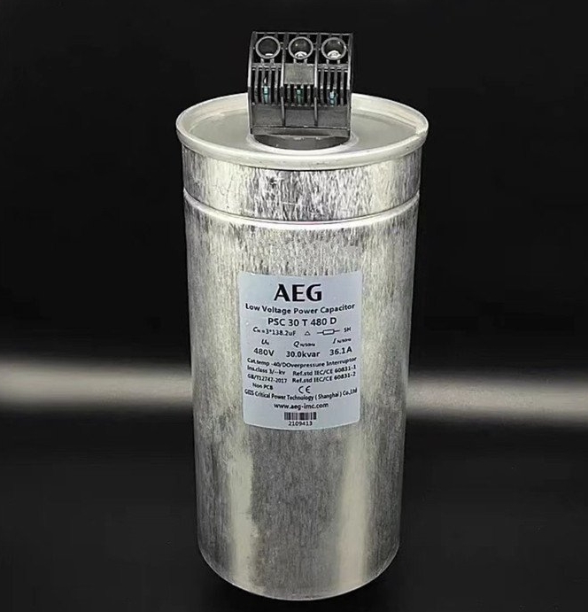
Reactive power compensation: In AC circuits, capacitors can enhance the power factor of the load and compensate for the phenomenon of power factor degradation caused by the widespread use of inductive loads.
Fast charging and discharging: Capacitors are extremely fast and can complete the charging and discharging process in an instant. This feature allows capacitors to shine in applications that require instantaneous high power output, such as acceleration and braking energy recovery in electric vehicles.
HOW TO CONNECT AC CAPACITORS
The method of wiring capacitors depends on their type and purpose. The following are common wiring methods and precautions:
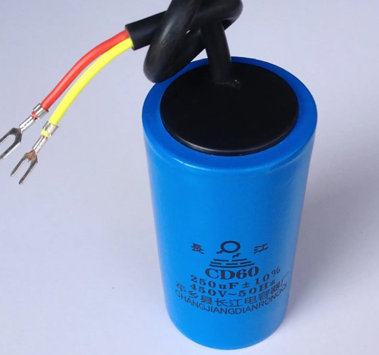
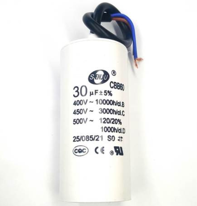
Distinguishing between types of capacitors
Polarized capacitors (e.g., electrolytic capacitors)
Positive (+): usually labeled with a “+” sign or with longer pins.
Negative (-): Shorter pins or black stripe/arrow markings on case.
Positive and negative markings are available:
The positive and negative terminals must be connected correctly, or the capacitor may be damaged, leak, or even explode.
Non-polarized capacitors (e.g., ceramic capacitors, polyester capacitors)
have no positive or negative polarity and can be connected at will.
Wiring Procedure
- DC Circuit (e.g. filtering, energy storage)
Polarized Capacitor:
Positive terminal is connected to the high potential end of the circuit (e.g. power supply positive terminal), negative terminal is connected to the low potential end (e.g. power supply negative terminal or ground).
If there is a reverse voltage in the circuit, it is necessary to change to a non-polarized capacitor or a series connection of two polarized capacitors (negative terminal connected).
Non-polarized capacitors:
are connected directly across where they are needed, with no need to differentiate between positive and negative terminals. - AC circuits (e.g., motor starting, coupling)
Non-polarized capacitors (e.g., AC capacitors) must be used; polarized capacitors must not be used.
The two ends of the capacitor are connected to the two ends of the alternating current (e.g., the fire wire and the zero wire). - Parallel and Series
Parallel:
Total capacity = sum of each capacitor’s capacity, with the smallest withstand voltage value.
Polarized capacitors in parallel, positive to positive, negative to negative.
Series:
Total capacity = 1/(1/C₁ + 1/C₂ + …), the withstand voltage value is added. The voltage withstand values are added together.
When polarized capacitors are connected in series, reverse connection (positive to negative) is required to offset the polarity.
Note:
Matching of withstand voltage value:
The withstand voltage value of the capacitor must be more than 1.5 times of the working voltage of the circuit to avoid breakdown.
Soldering Tips:
Use a soldering iron to solder quickly to avoid high-temperature damage to the capacitor.
Leave enough length for the pins to prevent stress damage.
Safe Operation:
In high-voltage circuits, the capacitor should be discharged after disconnecting the power supply (short the poles with a resistor) to prevent an electric shock.
Polarity check:
Use the capacitance file or diode file of the multimeter to measure the polarity (electrolytic capacitor forward resistance is large, reverse resistance is small).
Fourth, common errors
polarity reversal: lead to capacitor damage or explosion (electrolytic capacitors).
Insufficient withstand voltage: capacitor breakdown, short circuit, triggering circuit failure.
Wrong type: use of polarized capacitors in AC circuits, leading to capacitor failure.
If you are not sure of the wiring method, it is recommended to check the capacitor specification or consult a professional first.
How to Determine if an AC Capacitor is Damaged
Method 1: Using a Digital Multimeter with Capacitance Setting Function
- Disconnect the capacitor from the circuit to which it belongs.
- Read the capacitance value on the outside of the capacitor. Capacitance is measured in Farads and is expressed as a capital F. You may see the Greek letter μ. You may see the Greek letter μ (μ), which looks like a lowercase u preceded by a tail. (Because the farad is such a large unit, most capacitors measure capacitance in electrical microfarads; a microfarad is one millionth of a farad.)
- Set your multimeter to the capacitance setting.
The capacitance symbol usually shares a location on the dial with another function. - Connect the multimeter leads to the capacitor terminals. Connect the positive (red) multimeter lead to the capacitor anode lead and the negative (black) lead to the capacitor cathode lead. (On most capacitors, especially electrolytic capacitors, the anode lead is longer than the cathode lead.)
You may need to press the function button to initiate the measurement. - Check the multimeter reading. If the capacitance reading on the multimeter is close to the nominal value on the capacitor itself, the capacitor is good. If it is significantly less than the nominal value on the capacitor, or zero, the capacitor is damaged.
Method 2: Use a digital multimeter with no capacitance setting - Disconnect the capacitor from the circuit.
- Set your multimeter to resistance.
If your unit has an adjustable resistance range, set it to 1000 ohms = 1K or higher. - Connect the multimeter leads to the capacitor terminals. Again, connect the red wire to the positive (longer) terminal and the black wire to the negative (shorter) terminal.
- Observe the multimeter reading. If you wish, you can write down the initial resistance value. The value will quickly return to what it was before the leads were connected.
- Disconnect and reconnect the capacitor several times. If this is the case, then the capacitor is good.
However, if there is no change in the resistance value during the test, the capacitor is damaged.
Method 3: Using an analog multimeter - Disconnect the capacitor from the circuit.
- Set your multimeter to resistance measurement.
- Connect the multimeter leads to the capacitor terminals. Connect the red lead to the positive (longer) terminal and the black lead to the negative (shorter) terminal.
- Observe the results. An analog multimeter uses a pointer to display results. The behavior of the pointer determines whether the capacitor is good or not.
If the pointer initially shows a low resistance value and then tapers to infinity, then the capacitor is good.
If the pointer shows a low resistance value and does not move, the capacitor is shorted. You need to replace it.
If the needle shows no resistance and does not move, or if it shows a high resistance and does not move, the capacitor is an open-circuit capacitor (damaged).
Method 4: Testing the Capacitor with a Voltmeter - Disconnect the capacitor from the circuit.
- Check the voltage rating of the capacitor. Look for a number followed by a capital V, which is the symbol for volts.
- Charge the capacitor so that its voltage is less than, but close to, its voltage rating. For a 25V capacitor, you can use 9 volts, while for a 600V capacitor, you should use at least 400 volts. Allow the capacitor to charge for a few seconds. Make sure to connect the positive (red) lead from the voltage source to the positive (longer) terminal of the capacitor and the negative (black) lead to the negative (shorter) terminal.
The greater the difference between the capacitor’s nominal voltage and the charging voltage, the longer it will take to charge. In general, the higher the supply voltage you have access to, the easier it will be for you to test capacitors with higher voltage ratings. - Set your voltmeter to read DC voltages (if it is capable of reading AC and DC voltages).
- Connect the voltmeter leads to the capacitor. Connect the positive (red) lead to the positive (longer) end and the negative (black) lead to the negative (shorter) end.
- Record the initial voltage reading. This reading should be close to the voltage you are supplying to the capacitor. If it is not close, then this capacitor will not work well.
The capacitor will discharge its voltage into the voltmeter, and the longer it is connected, its reading will drop back to zero. This is normal. You should only be concerned if the initial reading is much lower than the expected voltage.
METHOD 5: SHORT CAPACITOR TERMINALS - Disconnect the capacitor from the circuit.
- Connect the wires to the capacitor. Again, connect the positive (red) lead to the positive (longer) terminal and the negative (black) lead to the negative terminal.
- Connect the wires to the power supply, but only for a short period.
- Disconnect the wires from the power supply.
- Short the terminals of the capacitor.
- Look at the sparks that are produced when you short-circuit the terminals. The possible sparks will indicate the capacity of the capacitor.
This method is only for capacitors that can store enough energy to produce a spark when shorted.
This method is not recommended because it can only be used to determine if the capacitor is capable of holding a charge and sparking when shorted, not to check if the capacitor’s capacity is within specification.
Using this method on larger capacitors may result in serious injury or even death!
Why AC capacitors fail
The main reasons for the failure of AC capacitors include the following:
Breakdown short-circuit: the main causes of capacitor breakdown include dielectric material blemishes or defects, dielectric electrical aging and thermal aging, electrochemical reactions within the dielectric, silver ions migrate, dielectrics in the Mechanical damage in the manufacturing process, high humidity or low air pressure environment between the poles flying arc, mechanical stress under the action of the dielectric transient short-circuit and so on.
Open circuit: the main causes of open circuit include “self-healing” of the lead parts, resulting in the insulation of the electrode and lead wire, oxidation of the contact surface of the lead wire and electrode, poor contact between the lead wire and electrode, corrosion and fracture of the lead foil of the anode of the electrolytic capacitor, drying or freezing of the liquid electrolyte, and transient open circuit of the dielectric under the action of mechanical stress. Dielectric transient open circuit, etc.
Changes in electrical parameters: changes in electrical parameters include excessively poor capacitance, increased tangent value of loss angle, decreased insulation performance or increased leakage current, etc. The main reasons are moisture or surface contamination, migration of silver ions, self-healing effect, electrical and thermal aging of the dielectric, volatilization and thickening of the working electrolyte, corrosion of the electrodes, the role of impurities and harmful ions, and the increase in the contact resistance between the lead wires and the electrodes etc.
Liquid leakage: the main causes of liquid leakage include the rise of air pressure inside the shell due to the release of gas from the impregnated material under the action of electric field, poor welding of the metal shell and sealing cover of the capacitor, poor welding of insulators and shell or leads, poor mechanical sealing of semi-sealed capacitors, insufficiently polished surface of the lead wires of the semi-sealed capacitors and corrosion of solder joints by the working electrolyte. The lead wire corrosion or breakage: the lead wire is corroded or broken.
Lead corrosion or fracture: lead corrosion or fracture of the main causes, including high temperature environment under the action of the electric field produced by electrochemical corrosion, electrolyte leakage along the lead caused by chemical corrosion, the lead manufacturing process by mechanical damage, and insufficient mechanical strength.
Insulator rupture: The main reasons for insulator rupture include mechanical damage, excessive residual heat in the sintering process of glass powder insulators, high welding temperature, or uneven heating etc.
Insulator surface flying arc: the main reasons for insulator surface flying arc include insulator surface moisture caused by surface insulation resistance drop, insulator design that is not reasonable, improper selection of insulators, and environmental air pressure that is too low.
Prevention and Detection Methods:
Regular Inspection and Maintenance: Regularly inspect the appearance and performance parameters of capacitors to detect and deal with potential problems in time.
Environmental control: Avoid exposing capacitors to extreme temperatures and humidity, and keep their working environment stable.
Correct use and maintenance: Avoid overloading and over-voltage use, and ensure that the capacitors are firmly and reliably installed and connected.
Quality Inspection: Strict quality control during the manufacturing process to ensure the quality and reliability of the capacitors.
AC Capacitor Replacement Costs
The cost of AC capacitor replacement varies depending on several factors, including the model, brand, and quality of the capacitor, as well as the ease of replacement. Reasons for Cost Differences
Models and Brands: Capacitors of different models and brands vary greatly in price. For example, a CBB65-450V-20uF capacitor costs $19, while the same model but with a capacity of 10uF costs $16.
Quality and performance: High-quality capacitors usually cost more, but their stability and durability are also better.
Replacement Difficulty: If capacitor replacement requires specialized tools or techniques, it may increase repair costs. For example, air conditioner capacitors may cost between $50 and-100 to replace, but replacement costs as high as $1,500 have been reported.
Specific Cost Examples
Ordinary Capacitors: Ordinary capacitors on the market are less expensive, usually ranging from a few dollars to a dozen dollars,
High-quality Capacitors: High-quality capacitors are more expensive, but have a long service life and High-quality capacitors: High-quality capacitors are more expensive, but have a long service life and stable performance.
Professional Repair Costs: The cost of a professional repairer’s visit usually includes the cost of the visit and the cost of materials; the total cost may range from 50 to 1500 yuan, depending on the complexity of the repair and the time required.