Resistors (commonly referred to simply as “resistors” in daily usage) are current-limiting components. When connected in a circuit, a resistor typically has a fixed resistance value with two pins that restrict the current flow in its connected branch. Resistors with unchangeable resistance values are called fixed resistors, while those with adjustable resistance are called potentiometers or variable resistors. An ideal resistor is linear, meaning the instantaneous current is directly proportional to the applied instantaneous voltage. Variable resistors used for voltage division feature one or two movable metal contacts pressed against an exposed resistive element, where the contact position determines the resistance between either end of the resistive element and the contact.
Table of Contents
Working Principle of PCB Resistors
Resistors on printed circuit boards function by impeding current flow through their internal resistive material, thereby limiting the current. Their operation is based on Ohm’s Law: V = I × R, where V is voltage, I is current, and R is resistance. A resistor’s fixed value is typically connected to the circuit through two pins to regulate current flow. The resistance value depends on factors including temperature, material, length, and cross-sectional area. The temperature coefficient quantifies resistance variation per 1°C temperature change, expressed as a percentage. A key characteristic of resistors is their ability to convert electrical energy into heat, making them energy-dissipating components. In circuits, resistors primarily serve voltage division and current splitting functions and can work with both AC and DC signals.
Resistor Materials
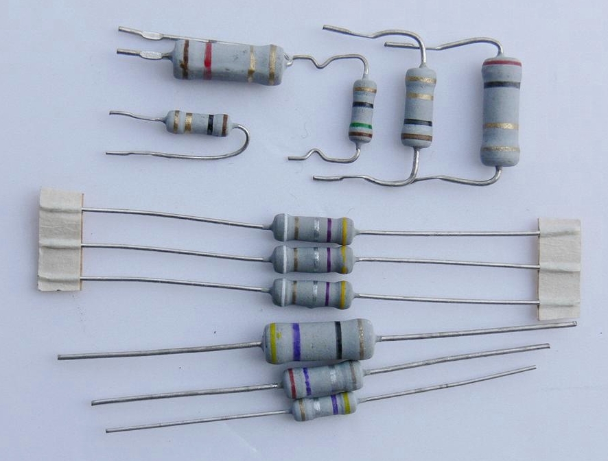
Resistors are primarily made from resistive materials, with common types including a carbon film, metal film, solid composition, and wire wound. These materials’ different properties determine resistor performance and applications. For example:
- Carbon film resistors are widely used due to their low cost and good stability
- Metal film resistors are preferred in high-performance circuits for their superior stability and low noise characteristics
Classification by Material
- Wirewound resistors: Made by winding high-resistance alloy wire around an insulating core, coated with heat-resistant glaze or insulating paint. Features low-temperature coefficient, high precision, good stability, and heat/corrosion resistance. Primarily used for precision high-power applications, though with poor high-frequency performance and large time constant.
- Carbon composition resistors: Formed by compressing carbon and synthetic plastic.
- Carbon film resistors: Created by depositing crystalline carbon on ceramic rods. Offer low cost, stable performance, wide resistance range, and low temperature/voltage coefficients, making them the most widely used resistor type.
- Metal film resistors: Produced by vacuum-depositing alloy materials on ceramic rods. Provide higher precision, better stability, lower noise, and smaller temperature coefficients than carbon film resistors, making them common in instrumentation and communication equipment.
- Metal oxide film resistors: Formed by depositing metal oxides (like tin oxide) on insulating rods. Being oxides themselves, they offer excellent high-temperature stability, thermal shock resistance, and strong load capacity.
By application, resistors can be categorized as general purpose, precision, high-frequency, high-voltage, high-resistance, high-power, and resistor networks.
Resistor Markings
The nominal resistance value is marked on resistors using numbers or color codes, with units of ohms (Ω), kilohms (kΩ), megohms (MΩ), or teraohms (TΩ). Resistance values follow standardized preferred number series corresponding to tolerance ratings.
Resistance Value and Tolerance Marking Methods
Three primary marking methods exist:
- Direct marking
- Color coding
- Alphanumeric symbol coding
1. Direct Marking Method
| Marking Example | Resistance Value | Tolerance |
|---|---|---|
| 3Ω3 Ⅰ | 3.3 Ω | ±5% |
| 1K8 | 1.8 kΩ | ±20% |
| 5M1 Ⅱ | 5.1 MΩ | ±10% |
| Note: Unmarked resistors default to ±20% tolerance |
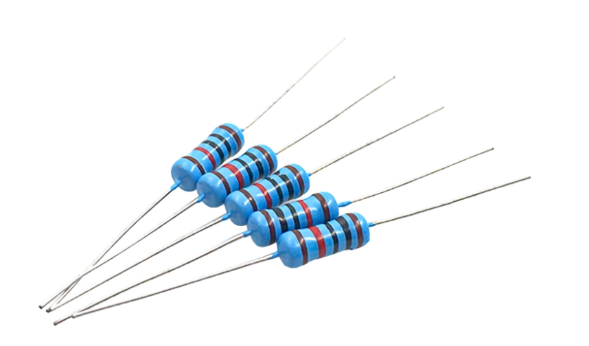
2. Color Coding Method
4-Band Resistor Identification
| Color | 1st Digit | 2nd Digit | Multiplier | Tolerance |
|---|---|---|---|---|
| Black | 0 | 0 | 10⁰ | — |
| Brown | 1 | 1 | 10¹ | — |
| Red | 2 | 2 | 10² | — |
| Orange | 3 | 3 | 10³ | — |
| Yellow | 4 | 4 | 10⁴ | — |
| Green | 5 | 5 | 10⁵ | — |
| Blue | 6 | 6 | 10⁶ | — |
| Violet | 7 | 7 | 10⁷ | — |
| Gray | 8 | 8 | 10⁸ | — |
| White | 9 | 9 | 10⁹ | — |
| Gold | — | — | 10⁻¹ | ±5% |
| Silver | — | — | 10⁻² | ±10% |
5-Band Resistor Identification
| Color | 1st Digit | 2nd Digit | 3rd Digit | Multiplier | Tolerance |
|---|---|---|---|---|---|
| Black | 0 | 0 | 0 | 10⁰ | — |
| Brown | 1 | 1 | 1 | 10¹ | ±1% |
| Red | 2 | 2 | 2 | 10² | ±2% |
| Orange | 3 | 3 | 3 | 10³ | — |
| Yellow | 4 | 4 | 4 | 10⁴ | — |
| Green | 5 | 5 | 5 | 10⁵ | ±0.5% |
| Blue | 6 | 6 | 6 | 10⁶ | ±0.25% |
| Violet | 7 | 7 | 7 | 10⁷ | ±0.1% |
| Gray | 8 | 8 | 8 | 10⁸ | ±0.05% |
| White | 9 | 9 | 9 | 10⁹ | — |
| Gold | — | — | — | 10⁻¹ | ±5% |
| Silver | — | — | — | 10⁻² | ±10% |
How to Use the Tables
For 4-band resistors:
- 1st band (tens digit): Color = Red (2)
- 2nd band (units digit): Color = Orange (3)
- Multiplier: Color = Black (10⁰)
- Tolerance: Color = Gold (±5%)
Example:
Red-Orange-Black-Gold = 23 × 10⁰ = 23Ω (±5%)
For 5-band resistors:
- 1st band (hundreds digit): Color = Red (2)
- 2nd band (tens digit): Color = Blue (6)
- 3rd band (units digit): Color = Green (5)
- Multiplier: Color = Black (10⁰)
- Tolerance: Color = Brown (±1%)
Example:
Red-Blue-Green-Black-Brown = 265 × 10⁰ = 265Ω (±1%)
Tolerance Definition
Tolerance represents the maximum allowable deviation between the actual resistance value and the nominal value, expressed as a percentage. Common tolerance grades include:
- Standard: ±5%, ±10%, ±20%
- Precision: <±1%
- High-precision: Up to ±0.001%
Note: Accuracy is determined by both tolerance and irreversible resistance changes.
Selection of PCB Resistors
1. Selection of Fixed Resistors
The choice of resistor material and construction should be based on the specific requirements of the application circuit:
- High-frequency circuits: Use non-wire-wound resistors with low distributed inductance and capacitance, such as carbon film, metal film, metal oxide film, thin film, thick film, alloy, or anti-corrosion coated resistors.
- High-gain small-signal amplifiers: Opt for low-noise resistors (e.g., metal film, carbon film, or wire-wound resistors). Avoid carbon composition and organic solid resistors, which exhibit higher noise.
Key Considerations:
✔ Select standard-series resistors with values closest to the calculated circuit requirement.
✔ General circuits: ±5% to ±10% tolerance is acceptable.
✔ Precision instruments/special circuits: Use high-precision resistors (e.g., 0.01%, 0.1%, or 0.5% tolerance, such as Jebsen resistors).
✔ Power rating must match circuit demands—avoid arbitrarily increasing/decreasing wattage.
✔ For power resistors: Choose a rating 1–2× higher than the actual circuit requirement.
2. Fusible Resistors
These function as protective components. Selection requires balancing:
- Normal operation: Stable performance under rated conditions.
- Overload scenarios: Rapid fusing to protect the circuit.
⚠ Improper resistance/power ratings will compromise protection.
Three Fundamental Selection Principles
- Certified Manufacturing: Choose resistors produced under high-standard certified processes.
- Supplier Evaluation: Prioritize manufacturers with technical superiority, quality assurance, cost efficiency, and reliable support.
- Direct Procurement: Source from approved suppliers with verified product catalogs.
Major Resistor Brands
| Region | Manufacturers |
|---|---|
| US/EU/Japan | Vishay, TE Connectivity, TT Electronics, Bourns, KOA |
| Taiwan/China | Yageo, Ralec, Uniohm, LIZ, TA-I, Walsin, Viking Tech, HKR, PAK HENG, TOKEN |
PCB Resistor Soldering Guidelines
1. Temperature Control
- Adjust based on resistor material, size, and soldering method.
- Too high: Risk of component damage.
- Too low: Weak solder joints.
2. Soldering Duration
- Excessive time: Degrades resistor performance.
- Insufficient time: Poor adhesion.
3. Placement
- Mount on the PCB’s top layer (avoid bottom-side placement).
- Minimize proximity to other components to prevent interference.
4. Soldering Methods
- Hand soldering: Low-volume prototyping.
- Machine soldering: Mass production.
- Both require strict control of temperature, time, and positioning.
5. Additional Checks
✔ Verify resistor specs match PCB design parameters.
✔ Pre-clean PCBs to remove contaminants.
✔ Post-soldering inspection: Ensure mechanical stability.
Summary: Proper resistor soldering is critical for PCB reliability. Mastery of these techniques ensures optimal circuit performance.