Table of Contents
What is a 5-pin relay?
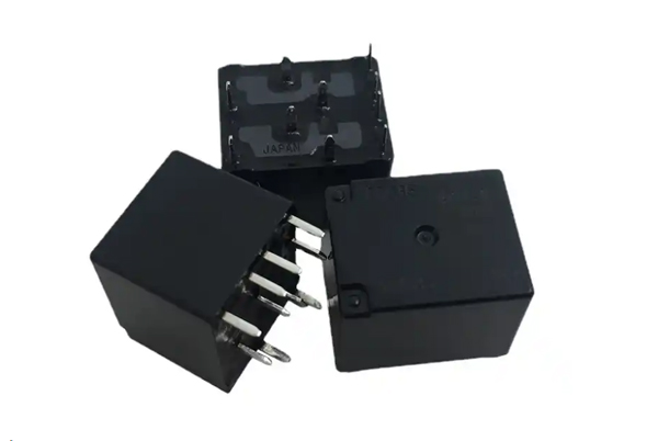
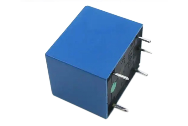
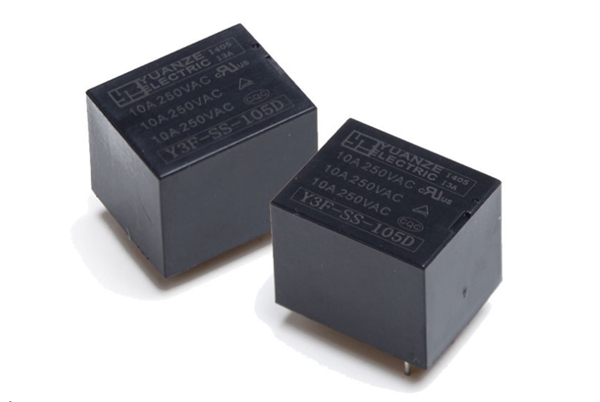
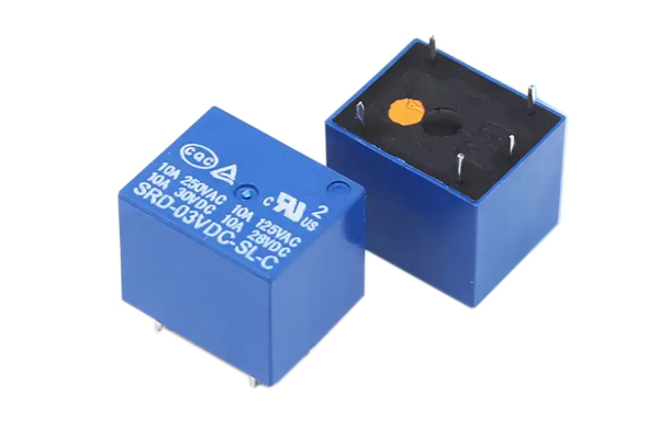
A 5-pin relay is an electronic control device with five pins, which is widely used in the switching control of various electronic circuits. The five pins correspond to different electrical connections, and the on-off control of the circuit is realized through the electromagnetic principle.
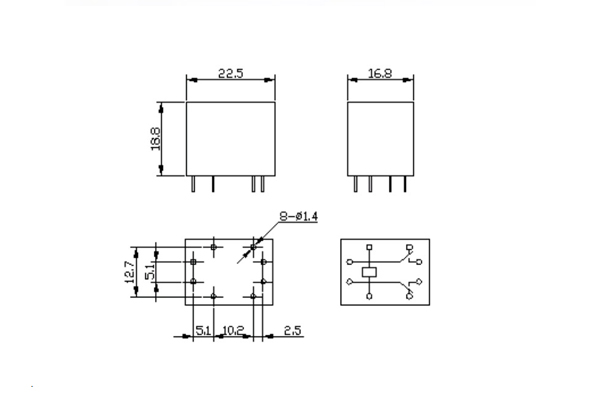
1.Structure
Iron core: as the core component of the electromagnetic system, it is responsible for conducting and concentrating magnetic lines of force.
Contact system: contains dynamic and static contacts, responsible for the on-off control of the main circuit.
Electromagnetic coil: generates electromagnetic force after energized, and drives the contact action.
Housing: provides mechanical protection and electrical insulation
2.Types
According to the contact configuration can be divided into
Single-contact type: a set of normally open or normally closed contacts.
Double-contact type: including normally open and normally closed two sets of contacts.
Multi-contact type: suitable for complex control scenarios.
In practical applications, it is necessary to select the appropriate relay model according to the load characteristics (current/voltage), control signal parameters and installation space and other factors. Special requirements such as vibration resistance and sealing should also be considered for special working conditions.
5-Pin Relay Pinout and Functions Explained
A 5-pin relay typically has five terminals labeled 30, 85, 86, 87, and 87a, each serving a specific electrical function as follows:
| Pin | Function | Typical Connection |
|---|---|---|
| 30 | Main power input, directly connected to the battery or fused power supply | Vehicle main power (+12V/24V) |
| 85 | Control circuit power input, receives signal from a switch or control module | Connected to a control switch (e.g., ignition switch, ECU signal) |
| 86 | Control circuit ground, completes the coil circuit with pin 85 | Connected to vehicle ground (chassis) |
| 87 | Normally Closed (NC) contact, connected to 30 when the relay is de-energized, and opens when energized | Connects to a default active load |
| 87a | Normally Open (NO) contact, disconnected from 30 when de-energized, and closes when energized | Connects to a load that activates only when powered |
Operation Logic
- De-energized state (coil not powered):
- 30 ↔ 87 closed (NC)
- 30 ↔ 87a open (NO)
- Energized state (85-86 powered, coil activated):
- 30 ↔ 87 opens
- 30 ↔ 87a closes
This design allows the 5-pin relay to perform circuit switching (e.g., headlights, fan control) while also supporting dual-load switching (e.g., high/low-speed fans, motor forward/reverse, etc.).
Advantages and Disadvantages of 5-Pin Relays
1.Key Advantages
- Multi-Circuit Control Capability
- Can control multiple independent circuits simultaneously for complex switching operations
- Supports both Normally Open (NO) and Normally Closed (NC) contact configurations
- High Load Capacity
- Typical load handling: 10-40A, suitable for high-power devices
- Compatible with various voltage levels (12V/24V/220V AC/DC)
- Wide Range of Applications
- Industrial automation control systems
- Automotive electronics (e.g., headlights, cooling fans)
- Smart home device control
- Power system protection equipment
2.Main Disadvantages
- Higher Wiring Complexity
- Requires correct identification of all 5 terminals (30/85/86/87/87a)
- Incorrect wiring may cause relay failure or equipment damage
- Often requires reference to wiring diagrams
- Cost Considerations
- Unit cost is 2-5 times higher than simple switches
- Additional wiring expenses for system integration
- Significantly higher price for high-current models
- Other Limitations
- Mechanical contacts have limited lifespan (~100,000 operations)
- Generates electromagnetic interference during switching
- Bulkier than solid-state relays
3.Usage Recommendations
Ideal for reliably controlling medium-to-high power loads. For low-power simple control applications, more economical solutions may be preferable. Professional installation should use clearly labeled terminals with proper insulation.
Working Principle of a 5-Pin Relay
A 5-pin relay operates through electromagnetic switching action, following this sequence:
- Default State (De-energized)
- The relay’s internal armature is held by a spring
- Terminal 30 connects to 87 (Normally Closed circuit)
- Terminal 30 disconnects from 87a (Normally Open circuit)
- Activation (Coil Energized)
- When power is applied across pins 85 (+) and 86 (-):
- The electromagnet coil generates a magnetic field
- The magnetic force overcomes the spring tension
- The armature physically moves, causing:
- 30 disconnects from 87 (NC circuit opens)
- 30 connects to 87a (NO circuit closes)
- Deactivation (Coil De-energized)
- When power is removed from the coil:
- The magnetic field collapses instantly
- The spring returns the armature to default position
- All contacts revert to their original state
Key Characteristics:
- Fast Switching: Typical response time 5-15ms
- Audible Click: Mechanical movement produces characteristic sound
- Isolated Control: Low-power coil circuit (typically 12V/24V DC) controls high-power load circuit (up to 40A)
5-Pin Relay Connection Guide (Safe Installation Procedure)
1. Safety Preparation
- Power Isolation: Verify all power sources are disconnected using a multimeter
- Tool Preparation: Prepare insulated tools (12V test light, wire strippers)
- Relay Inspection: Check relay specifications (coil voltage/current, contact rating)
2. Standard Wiring Procedure
| Connection Point | Wiring Specification |
|---|---|
| Pin 30 | Connect to fused power source (max current ≤ relay rating) |
| Pin 85 | Link to control switch output (positive trigger) |
| Pin 86 | Route to reliable ground point (resistance <0.5Ω) |
| Pin 87 | Wire to NC (Normally Closed) load device |
| Pin 87a | Connect to NO (Normally Open) load device |
3. Enhanced Protection Measures
- Overcurrent Protection: Install fast-blow fuse (125% of load current) on Pin 30
- Voltage Suppression: Add flyback diode (1N4007) across coil pins (85-86)
- Contact Protection: Parallel RC snubber circuit (100Ω + 0.1μF) for inductive loads
4. Verification & Testing
- Pre-energization Check:
- Continuity test between 30-87 (should show 0Ω)
- Open circuit between 30-87a (should show ∞Ω)
- Operational Test:
- Apply control voltage (measure coil current 40-100mA typical)
- Verify contact transition (audible click within 20ms)
- Load current measurement (should match device specs)
Professional Tips:
- For automotive applications: Use relay socket with IP67 rating
- High-vibration environments: Apply thread locker to terminal screws
- Critical systems: Implement redundant relay configuration
How to test a 5-pin relay
The method of measuring the good or bad of the five-pin relay mainly includes the following steps:
1. Identify the pins
First, you need to identify the two coil pins and three contact pins of the five-pin relay. The coil pins usually have a high voltage (e.g. 12V or 24V), while the contact pins have a relatively low voltage (0-5V range).
2. Measuring contact resistance
Using the resistance setting of a multimeter, measure the resistance of each contact in relation to the other contacts and to itself. Under normal circumstances, any two contacts should show a great resistance between them, indicating that they do not form a pathway. If the resistance is low, a short circuit may exist. At the same time, a single contact on its own resistance should also be great, otherwise it may indicate that the contact and the relay shell there is a short circuit.
3. Detecting coil voltage
Detect the voltage across the coil pins by using the voltage gear of the multimeter. If voltage is detected, the coil is in good condition; if no voltage is shown, it may mean that the coil is disconnected.
4. Functional Test
If all the above measurements are as expected, the relay can be connected to the circuit for further functional testing to see if it can properly engage and release the contacts.
Please pay attention to the following matters during the measurement:
Ensure that the measurement is carried out in a power-off state to avoid the danger of electric shock.
Keep both hands and the multimeter probe insulated from the metal parts of the relay during measurement.
If abnormal conditions are found, such as abnormal resistance value, no voltage, etc., the relay or related circuits should be further checked.
5-Pin Relay Applications in PCBA Design
1. Layout Considerations
- Strategic Placement:
- Position near board edge for serviceability
- Minimum 5mm clearance from sensitive analog circuits
- Orientation parallel to power traces to minimize loop area
- Thermal Management:
- Avoid placement near heat-generating components
- Provide adequate copper relief for coil power dissipation
2. Electrical Interconnection
- Terminal Routing:
- 30-40mil trace width for load-carrying paths (10A+)
- Separate high-current (>5A) and signal-level routing layers
- Implement star-point grounding for coil/common terminals
- Protection Circuits:
- TVS diodes for inductive load switching
- ARC suppression for contacts (RC networks/MOVs)
3. Driver Circuit Implementation
| MCU Type | Driver Solution | Current Gain |
|---|---|---|
| STM32F1 | 2N7002 MOSFET | 20:1 |
| STM32H7 | ULN2003 Darlington | 50:1 |
| ESP32 | BSS138 Logic-Level FET | 15:1 |
Design Notes:
- Include base/gate resistors (1-10kΩ)
- Implement flyback diodes (1N4148 for <500mA)
- Provide driver IC decoupling (100nF ceramic)
4. EMI Mitigation Techniques
- Board-Level Solutions:
- Guard rings around relay coil
- Four-layer stackup with dedicated ground plane
- Ferrite beads on coil supply lines
- Component Selection:
- Opt for sealed relay models (RT1 series)
- Prefer gold-plated contacts for low-noise switching
- Select low-EMI variants with built-in suppression
5. Load Matching Methodology
Selection Matrix:
| Parameter | Industrial Standard | Automotive Grade | Consumer Grade |
|---|---|---|---|
| Contact Rating | 10A@250VAC | 15A@14VDC | 5A@120VAC |
| Mechanical Life | 100,000 ops | 50,000 ops | 10,000 ops |
| Operating Temp | -40°C~85°C | -40°C~125°C | 0°C~70°C |
Validation Protocol:
- Inrush current testing (10x nominal)
- Contact bounce measurement (<5ms)
- Thermal imaging at 100% duty cycle
Design Verification:
- Perform HALT testing (85°C/85%RH)
- Conduct EMC pre-compliance scans
- Validate MTBF predictions via MIL-HDBK-217F
Note: For high-density designs, consider SMD relay alternatives (e.g., TQ2-L2 series) with compatible footprints. Always perform design-for-manufacturing (DFM) review with your PCB assembler.
5 Safety Guidelines for Pin Relays
1. Electrical Parameter Matching Principles
- Voltage Compatibility:
- Strictly verify coil rated voltage (±10% tolerance)
- Standard specifications: 12VDC/24VDC/220VAC
- Current Capacity:
- Contact current must not exceed rated value (recommend 80% derating)
- Reference standards:
- Resistive load: 100% rated value
- Inductive load: 50% rated value
- Wire Gauge Selection:Load CurrentMinimum CSARecommended AWG≤5A0.5mm²AWG205-10A1.0mm²AWG1810-20A2.5mm²AWG14
2. Installation Standards
- Mechanical Mounting:
- Use DIN rail mounting (compliant with IEC60715)
- Install anti-vibration washers in high vibration environments
- Electrical Isolation:
- Maintain ≥6mm spacing between high/low voltage terminals
- Install insulating sleeves on high-voltage lines
- Thermal Management:
- Provide ≥20mm clearance for heat dissipation
- Maintain ≥15mm spacing between multiple relays
3. Operation and Maintenance
- Periodic Inspection Items:
- Monthly: Contact resistance measurement (≤100mΩ)
- Quarterly: Coil insulation test (≥10MΩ)
- Annually: Mechanical operation test (operating force ≤1.5N)
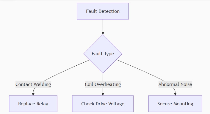
- Fault Handling Procedure:
3. Environmental Control:
- Humidity range: 20%-85%RH (non-condensing)
- Dust protection: IP40 or higher
4. Safety Operation Procedures
- Power-off Sequence:
- Disconnect load power
- Verify de-energization with voltage tester
- Install “Do Not Operate” tag
- Wait 5 minutes (capacitive load discharge)
- Disassembly Precautions:
- Use ESD-safe tools
- Remove load terminals before control terminals
- Label all terminals (recommend photographic documentation)
5. Failure Prevention Measures
- Contact Protection:
- DC loads: Parallel freewheeling diode
- AC loads: Install RC snubber circuit (0.1μF+100Ω)
- Life Extension Strategies:
- Avoid frequent switching (<10 operations/minute)
- For high-current loads, recommend pre-connection contactor
Note: Per UL508 standards, industrial relays should be preventively replaced every 50,000 operations or 3 years (whichever comes first). In critical power systems, redundant configuration should be implemented to achieve SIL2 reliability requirements.
5-Pin Relay Application Scope
- Home Automation Projects
In home automation projects, 5 pin relays are commonly used to switch AC loads, such as controlling the switching of lights, outlets and other devices. - Industrial control
In industrial control, 5-pin relays are used to control the start and stop of large equipment or machines to ensure the normal operation and safety of the equipment. - Automotive electronics
In automotive electronics, 5-pin relays are used to control indicator lights, glass lifters, etc. to improve the safety and comfort of vehicles. - Safety Circuit
In safety circuits, 5-pin relays are used to disconnect the load from the power supply in the event of a malfunction, ensuring the safety of the system.