1.Difference between four-pin and five-pin relay definitions
Table of Contents
What is a 4-pin relay?
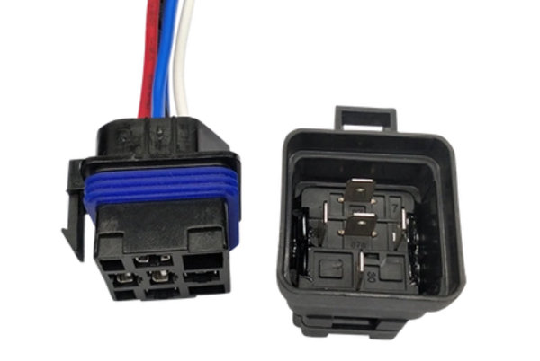
The four-pin relay is a single-pole, single-throw (SPST) type electromagnetic relay that consists of two parts: a coil control system and a contact system. The relay utilizes a standard pin configuration: 85 and 86 are the coil control terminals and 30 and 87 are the contact terminals. In the unenergized state, the contacts remain normally open (NO) mode, and pins 30 and 87 are disconnected; when the rated voltage is applied to the coil terminal, the electromagnetic mechanism operates to make the moving and static contacts close, and pins 30 and 87 conduct to form a circuit. After power failure, the spring reset mechanism automatically restores the normally open state, realizing fast circuit breaking.
What is a 5-pin relay?
The five-pin relay is a single-pole, double-throw (SPDT) type electromagnetic relay that allows bi-directional circuit switching with the synergistic action of the coil control terminals (85, 86) and contact terminals (30, 87, 87a).
Compared with four-pin relays, five-pin relays can meet more complex control needs with their dual circuit switching capability and state feedback characteristics, and are widely used in electrical systems requiring multi-state switching or fault protection.
2. Structural Design and Functional Differences
1. 4-Pin Relay (SPST Type)
- Core Structure:
- Coil Terminals: 85/86 (Standard drive voltage: 5-48VDC)
- Contact Terminals: 30 (Common) – 87 (Normally Open, NO)
- Operational Characteristics:
- Default State: 30-87 open circuit
- Energized State: 30-87 closed (single-path switching)
- Design Feature: No state retention, pure two-state switching
2. 5-Pin Relay (SPDT Type)
- Core Structure:
- Coil Terminals: 85/86 (Compatible with 4-pin drive voltage)
- Contact Terminals: 30 (Common) – 87 (NO) – 87a (Normally Closed, NC)
- Operational Characteristics:
- Default State: 30-87a closed, 30-87 open
- Energized State: 30-87 closed, 30-87a open
- Design Feature: Triple-terminal switching with state memory
▶ Key Difference: The 87a terminal enables “Break-before-Make” operation (typical switching time <3ms), preventing transient short circuits during switching.
3. Electrical Parameters and Reliability Comparison
| Parameter | 4-Pin Relay | 5-Pin Relay |
|---|---|---|
| Contact Rating | ≤40A (resistive load) | ≤30A (per contact) |
| Isolation Voltage | 1.5kV (coil-contact) | 3kV (coil-contact) |
| Contact Resistance | 20mΩ (silver alloy) | 35mΩ (dual-path) |
| Mechanical Life | 10^6 cycles (@10A) | 5×10^5 cycles (@10A) |
| Operating Frequency | ≤0.5Hz | ≤2Hz |
Data Insight:
- 4-pin excels in high-load cycling (e.g., industrial motor control)
- 5-pin dominates high-frequency switching and safety isolation (e.g., automotive lighting)
4. Application Scenario Analysis
4-Pin Preferred Cases:
✓ Unidirectional switching (lighting/power circuits)
✓ Space-constrained designs (PCB area <100mm²)
✓ Cost-sensitive projects (30% BOM reduction)
5-Pin Mandatory Cases:
✓ Dual-state control (motor reversal/headlight beam switching)
✓ Fail-safe systems (87a as safety loop)
✓ Smart devices with state feedback (self-diagnosis via 87a)
Industry Data:
- Automotive: 65% 5-pin adoption (driven by ADAS)
- Industrial: 72% 4-pin dominance (reliability-critical)
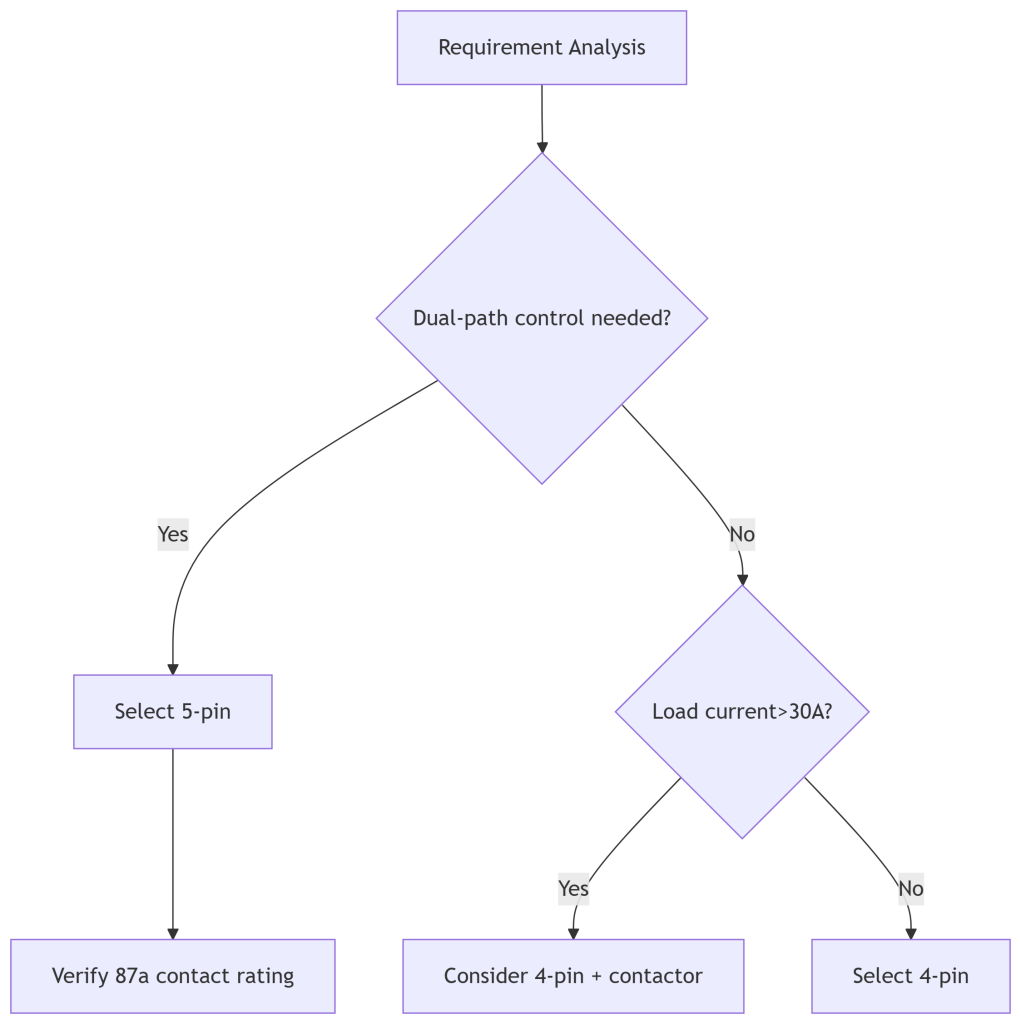
5. Selection Decision Flowchart
6. Design Risk Mitigation
4-Pin Limitations:
- Voltage spikes: Add RC snubber (100Ω+0.1μF recommended)
- No state feedback: External current sensor (e.g., ACS712)
5-Pin Advantages Enhancement:
- Leverage 87a for:
- Hardware interlock (galvanic isolation)
- Power-on self-test (MCU-based state verification)
7. Technology Trends
- 4-Pin: HV-DC adaptation (EV-compatible 1000VDC versions)
- 5-Pin: Integrated diagnostics (e.g., TE Connectivity IMRS series)
Recommendation: Prioritize contact life validation (per IEC 61810-7).