Table des matières
Qu'est-ce qu'un circuit imprimé à base de métal ?
Une carte de circuit imprimé à base métallique (Metal Core PCB, abrégée MCPCB) est une solution innovante qui utilise un matériau métallique comme substrat. Comparée aux substrats FR-4 traditionnels, la MCPCB utilise sa structure unique à substrat métallique pour transférer efficacement la chaleur générée pendant le fonctionnement du circuit depuis les zones critiques vers les zones non critiques, telles que les dissipateurs thermiques ou le substrat métallique lui-même, offrant ainsi une gestion thermique exceptionnelle.
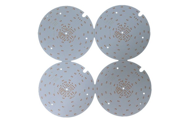
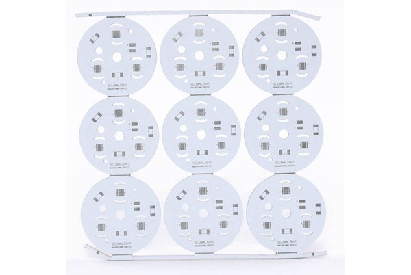
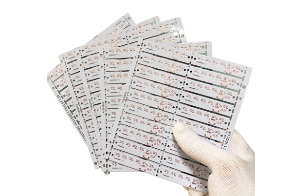
Parmi ceux-ci, le substrat en aluminium fourni par TOPFAST Il s'agit d'une catégorie importante de circuits imprimés à base de métal, relevant du domaine technique des stratifiés à base de métal recouverts de cuivre. Ce produit utilise un matériau en aluminium de haute qualité comme substrat de base, combinant parfaitement une excellente conductivité thermique et des propriétés d'isolation fiables. Il est particulièrement adapté aux applications nécessitant une dissipation thermique rigoureuse, telles que l'éclairage LED et les modules d'alimentation. Grâce à des processus de production avancés et à un contrôle qualité strict, TOPFAST propose des solutions de substrats en aluminium hautement performantes et fiables.
Analyse de la structure des circuits imprimés à noyau métallique (MCPCB)
Les circuits imprimés à noyau métallique (MCPCB), également appelés substrats métalliques isolés (IMS) ou circuits imprimés métalliques isolés (IMPCB), sont conçus selon le principe fondamental d'une dissipation thermique efficace. Leur structure multicouche typique se caractérise par une répartition symétrique des couches. Par exemple, dans une carte à 12 couches, le noyau métallique est positionné au centre, flanqué de manière uniforme de six couches non métalliques de chaque côté afin d'assurer la stabilité structurelle et un transfert de chaleur équilibré.
Composants structurels essentiels
La structure stratifiée du MCPCB se compose principalement des éléments clés suivants :
- Couche circuit : This is the copper foil layer responsible for electrical connections. To meet high-current transmission requirements, TOPFAST MCPCB utilizes thick copper foil designs, with standard thicknesses ranging from 35 μm to 280 μm, ensuring both current-carrying capacity and reliability.
- Couche d'isolation thermique : Il s'agit de la technologie de base du substrat en aluminium. Généralement composée d'un polymère spécial rempli de particules céramiques, cette couche offre une excellente conductivité thermique, une résistance électrique élevée et une grande résilience mécanique. TOPFAST utilise des systèmes de matériaux haut de gamme, tels que ceux similaires à IMS-H01 et LED-0601, pour cette couche isolante. Ces matériaux présentent une résistance thermique minimale, transfèrent efficacement la chaleur et résistent aux contraintes thermiques à long terme afin de garantir la longévité du produit.
- Couche de base métallique : Servant de support structurel et de principale voie de dissipation thermique, cette couche est généralement constituée d'aluminium hautement thermoconducteur ou de cuivre encore plus conducteur. Les plaques de base métalliques de TOPFAST offrent non seulement des performances thermiques supérieures, mais conviennent également à des usinages mécaniques de précision tels que le perçage et le poinçonnage afin de répondre à des exigences d'application complexes.
Substrat en aluminium TOPFAST : intégration de performances supérieures
Les substrats en aluminium de TOPFAST sont des produits représentatifs dans la catégorie des stratifiés à base de métal recouverts de cuivre, alliant une excellente conductivité thermique, une isolation électrique fiable et une excellente aptitude à la transformation mécanique. Nous respectons strictement les normes de traitement de surface telles que le placage à l'or, l'immersion dans l'or, la pulvérisation d'étain (y compris les procédés sans plomb) et l'anti-oxydation OSP, garantissant que chaque carte conserve des performances élevées et une longue durée de vie, même dans des conditions difficiles.
Types et avantages des circuits imprimés à âme métallique
Les circuits imprimés à âme métallique comprennent principalement trois types : les circuits imprimés à base d'aluminium, à base de cuivre et à base de fer. Le tableau suivant présente une comparaison détaillée des principales caractéristiques des circuits imprimés à base d'aluminium et à base de cuivre, ainsi qu'un résumé systématique des avantages techniques généraux de cette catégorie de circuits imprimés.
| Aspect | Circuit imprimé à base d'aluminium | Circuit imprimé à base de cuivre |
|---|---|---|
| Caractéristiques fondamentales | Choix équilibré en termes de coût, de poids et de performances | Conductivité thermique et performances de haut niveau pour les conditions extrêmes |
| Conductivité thermique | 5 – 2.0 W/(m·K) | Up to 386 W/(m·K) |
| Coefficient de dilatation thermique | Approx. 25 μm/m°C | Approx. 17 μm/m°C |
| Épaisseur typique du substrat | 2 à 8 mm | Personnalisé en fonction des exigences de conception |
| Résistance au pelage | > 9 lb/po | > 9 lb/po |
| Tension de claquage | > 3000 V | > 3000 V |
| Indice de résistance au feu | UL 94V-0 | UL 94V-0 |
| Principaux avantages | • Excellent thermal conductivity and dissipation • Relatively lightweight • Recommandation TOPFAST : choix économique | • Superior thermal performance • Better thermal stability • Solution TOPFAST : conçue pour répondre aux besoins de haute performance |
| Types courants | Circuits imprimés en aluminium à couche unique, double couche ou multicouche | Cuivre fritté, cuivre intégré, plaques froides, etc. |
Avantages techniques complets des circuits imprimés à noyau métallique
| Avantage | Description | Valeur pour les clients |
|---|---|---|
| Dissipation thermique efficace | Thermal conductivity (1-7 W/m·K) is 8-9 times that of FR-4, rapidly reducing component operating temperatures. | Augmente la densité de puissance du produit, prolonge la durée de vie de l'appareil et améliore la fiabilité à long terme. |
| Robustesse structurelle | La couche centrale métallique offre une résistance mécanique élevée, avec une forte résistance aux chocs et aux vibrations. | Produits TOPFAST sont particulièrement adaptés aux environnements difficiles tels que les applications automobiles et industrielles. |
| Flexibilité de la conception | La couche métallique peut être gravée dans des dissipateurs thermiques personnalisés (par exemple, ceux de TOPFAST). Structure intégrée de dissipation thermique), simplifiant ainsi la conception du système. | Économise l'espace et les coûts associés aux composants externes de dissipation thermique, permettant ainsi de concevoir des produits plus compacts. |
| Haute fiabilité | Le faible coefficient de dilatation thermique réduit les contraintes thermiques, minimisant ainsi considérablement la fatigue des joints de soudure et les risques de séparation des composants. | Réduit les taux de défaillance sur le terrain, diminue les coûts de maintenance et préserve la réputation de la marque. |
| Matériaux écologiques | Les substrats métalliques (aluminium, cuivre) sont recyclables, ce qui correspond aux tendances en matière de fabrication écologique. | Aide les clients à se conformer aux réglementations environnementales et à se forger une image de marque écologique. |
Spécifications du processus de fabrication des circuits imprimés à noyau métallique
I. Conception de la structure de laminage
- Une structure de stratification symétrique est adoptée afin d'assurer une répartition équilibrée des couches des deux côtés de la couche métallique.
- Maintenir une répartition symétrique de la couche de cuivre afin d'éviter toute déformation de la carte.
- Standard dielectric layer thickness: 0.003–0.006 inches.
II. Exigences particulières relatives au processus
- Traitement des trous métallisés: Les pièces métalliques doivent subir un traitement d'isolation.
- Processus de forage: Des scies à métaux à revêtement diamanté sont utilisées.
- Processus du masque de soudure: L'encre blanche pour masque de soudure est préférable pour les cartes LED.
III. Spécifications techniques détaillées
1. Spécifications relatives à la conception des bordures
- Maintain a minimum distance of ≥1.5mm between the aluminum board edge and SMD component silkscreen/plug-in hole pin edges.
- Internal and external slot chamfer range: 0.8–1.0mm.
- Ouvrez un emplacement complet lorsque la distance entre les parois des trous des composants est inférieure à 1,15 mm.
- Épaisseur standard des panneaux en aluminium : 1,5 mm (maximum ne dépassant pas 8 mm).
- For thickness >1mm, the narrowest border dimension should be ≥3mm.
- For thickness <1mm, the narrowest border dimension should be ≥5mm.
2. Options de traitement de surface
- Plusieurs procédés disponibles : HASL, ENIG, placage à l'or, etc.
- Le HASL n'est pas recommandé pour les cartes à base de cuivre.
IV. Spécifications de processus pour divers circuits imprimés à noyau métallique
Circuit imprimé à noyau métallique simple face
| Type de processus | Spécifications de forage | Exigences particulières |
|---|---|---|
| Laminage PP | ① Aspect ratio 10:1 ② Component holes ≥0.8mm ③ Vias 0.3–0.8mm | Counterbore ≥1.0mm Angle 82–165° |
| Liaison diélectrique | ① Hole wall spacing ≥0.5mm ② Component holes ≥0.8mm ③ Vias 0.3–0.8mm | Metal core tolerance ±0.1mm |
Champ d'application: Éclairage LED et autres scénarios nécessitant une dissipation thermique.
Circuit imprimé à double face/multicouche à âme métallique
- Spécifications de forage :
- Rapport d'aspect 10:1
- Component holes ≥1.0mm
- Vias 0.3–0.8mm
- Board thickness range: 0.8–3.5mm (maximum 8mm)
Champ d'application: Équipements de communication, systèmes de contrôle électroniques.
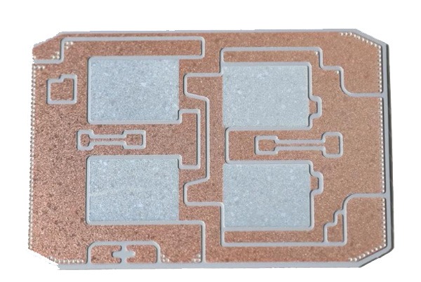
Circuit imprimé à noyau métallique fritté
- Spécifications du bloc de cuivre :
- Épaisseur : 1,0/1,5/2,0/3,0 mm
- Area: 50×50mm to 200×200mm
- Points clés de la conception :
- Les zones de connexion doivent comporter du cuivre apparent.
- At least one 0.3mm vent hole per 20×20mm area.
- Masques de soudure pour empêcher l'écoulement de la soudure.
- Procédé de traitement de surface : ENIG (prend en charge 2 cycles de refusion).
Champ d'applicationSolutions de dissipation thermique pour composants haute puissance.
Circuit imprimé à noyau métallique en cuivre intégré
- Exigences relatives aux blocs de cuivre :
- Size: 3×3mm to 60×80mm
- Thickness: 1.0–3.0mm
- Spacing: ≥7mm
- Limites du processus :
- Zone d'exclusion de 20 mil autour des blocs de cuivre.
- Le HDI et le bouchage à la résine ne sont pas pris en charge après la stratification.
- Lamination cycles ≤2.
Champ d'application: Scénarios nécessitant une dissipation thermique localisée élevée.
Procédé à plaque froide
- Épaisseur standard de la plaque d'aluminium : 1,5 mm
- Les règles de perçage suivent les spécifications standard des circuits imprimés.
- Prend en charge les procédés HASL, ENIG et de placage à l'or.
Champ d'application: Domaines à haute fiabilité tels que l'aérospatiale et les modules d'alimentation électrique.
Circuit imprimé rigide-flexible à âme métallique
- Combine les avantages des noyaux métalliques rigides et des circuits flexibles.
- Component holes require ≥1.2mm.
- Prend en charge diverses structures, notamment les plaques froides, les plaques frittées et le cuivre intégré.
Champ d'application: Applications nécessitant à la fois une dissipation thermique et une flexibilité d'assemblage.
V. Résumé des avantages du processus
Grâce au contrôle professionnel des processus de TOPFAST, les circuits imprimés à noyau métallique garantissent :
- Excellentes performances en matière de gestion thermique.
- Résistance mécanique supérieure.
- Capacité d'adaptation à des environnements complexes.
- Répondre aux exigences d'installation à haute densité.
Tous les processus sont soumis à un contrôle qualité rigoureux, offrant ainsi aux clients des solutions fiables en matière de dissipation thermique.
Analyse comparative complète des circuits imprimés à noyau métallique par rapport aux circuits imprimés FR-4
Comparaison des caractéristiques principales
| Caractéristique | Circuit imprimé à noyau métallique (MCPCB) | Circuit imprimé FR-4 |
|---|---|---|
| Conductivité thermique | 1-7 W/m·K | 0.3-0.4 W/m·K |
| Résistance structurelle | Haute rigidité, excellente résistance aux vibrations | Rigidité moyenne |
| Gestion thermique | Conduction thermique directe à travers la couche métallique | S'appuie sur des vias thermiques |
| Niveau de coût | Relativement élevé | Rentabilité |
| Traitement | Exigences particulières en matière de découpe | Flux de processus standard |
Différences matérielles et structurelles
PCB à noyau métallique
- Matériau de base : substrat métallique en aluminium ou en cuivre
- Structure : composite à trois couches (feuille de cuivre + couche diélectrique + noyau métallique)
- Traitement de surface : revêtements isolants tels que l'oxyde d'aluminium
- Solution TOPFAST: Fournit une conception optimisée de la structure stratifiée.
Circuit imprimé FR-4
- Matériau de base : résine époxy renforcée de fibres de verre
- Structure : prend en charge des conceptions flexibles, de simple à multicouche
- Caractéristiques : performances diélectriques stables, grande adaptabilité au traitement
Analyse approfondie des paramètres de performance
Performance thermique
- Circuit imprimé à noyau métallique : conductivité thermique environ 600 fois supérieure à celle du FR-4, adapté aux scénarios nécessitant une dissipation thermique élevée.
- FR-4 PCB: Poor thermal conductivity, glass transition temperature 130-180°C
Caractéristiques mécaniques
- Circuit imprimé à âme métallique : épaisseur comprise entre 0,8 et 4 mm, excellente résistance mécanique
- Circuit imprimé FR-4 : épaisseur comprise entre 0,2 et 5 mm+, bonne flexibilité de traitement
Analyse coûts-avantages
PCB à noyau métallique
- Coût des matériaux : plus élevé en raison du substrat métallique et des couches isolantes spéciales
- Coût du processus : équipement de traitement spécialisé, grande complexité du processus
- Valeur TOPFAST: Contrôle des coûts grâce à des processus de production optimisés
Circuit imprimé FR-4
- Coût des matériaux : matériaux de base abordables, adaptés à la production en série
- Coût du processus : processus mature, effets d'échelle significatifs
Guide des scénarios d'application
Applications des circuits imprimés à noyau métallique
- Systèmes d'éclairage LED haute puissance
- Modules de conversion de puissance
- Systèmes électroniques de commande pour véhicules automobiles
- Entraînements industriels pour moteurs
- Expertise TOPFAST: Solutions personnalisées pour les exigences élevées en matière de dissipation thermique
Applications des circuits imprimés FR-4
- Ordinateurs et périphériques
- Infrastructure de communication
- Electronique grand public
- Contrôle industriel général
Stratégie de sélection des circuits imprimés à noyau métallique
En fonction des exigences en matière de dissipation thermique
- Aluminum substrate: Thermal conductivity 1.0-6.0 W/(m·K), optimal cost-performance
- Copper substrate: Thermal conductivity ~388 W/m·K, high-performance choice
- Ceramic substrate: Thermal conductivity 150-220 W/(m·K), special applications
En fonction de l'environnement d'exploitation
- Environnement à haute température : carte FR-4 à haute Tg ou substrat en aluminium
- Environnement conventionnel : matériau FR-4 standard
Basé sur les performances électriques
- Applications haute fréquence : matériaux haute fréquence spécialisés
- Applications conventionnelles : matériaux FR-4 standard
Basé sur les exigences mécaniques
- Exigences en matière de légèreté : le substrat en aluminium présente des avantages évidents.
- Scénarios sensibles aux coûts : évaluation complète des coûts du cycle de vie
Points clés pour la prise de décision en matière de sélection
- Définir les exigences fondamentales: Performances en matière de dissipation thermique par rapport au contrôle des coûts
- Évaluer l'environnement d'exploitation: Plage de température, conditions de vibration
- Analyser les exigences en matière de signal: Caractéristiques de fréquence, contrôle d'impédance
- Prendre en compte les facteurs liés à la fabrication: Faisabilité du processus, cycle de livraison
- Tirez parti d'un soutien professionnel: TOPFAST fournit des conseils techniques complets
Grâce à des processus d'évaluation systématiques et à une sélection professionnelle des matériaux, la solution PCB la plus adaptée peut être choisie pour des applications spécifiques, permettant ainsi d'atteindre un équilibre optimal entre performances, fiabilité et coût.
Comment choisir le circuit imprimé à noyau métallique adapté à des applications spécifiques
Le choix d'un circuit imprimé à noyau métallique (MCPCB) nécessite un cadre d'évaluation systématique.
I. Dimensions fondamentales de la sélection
1. Exigences en matière de performances thermiques
- Substrat d'aluminium: Thermal conductivity 1.0-6.0 W/(m·K), optimal cost-performance
- Convient pour : éclairage LED haute puissance, modules de conversion de puissance
- Substrat en cuivre: Thermal conductivity ~388 W/(m·K), excellent heat dissipation
- Convient pour : Électronique automobile, lasers haute puissance
- Substrat céramique: Thermal conductivity 150-220 W/(m·K), excellent high-frequency characteristics
- Convient pour : modules de puissance IGBT, SiC
2. Température ambiante de fonctionnement
- Environnement à haute température (>150°C): Aluminum substrate or FR-4 high Tg material
- Environnement conventionnel: FR-4 standard suffisant
3. Exigences en matière d'intégrité du signal
- Applications haute fréquence: Choisissez des matériaux haute fréquence en PTFE ou Rogers.
- Applications conventionnelles: Le FR-4 standard offre un meilleur avantage en termes de coût.
II. Solutions alternatives de dissipation thermique pour les circuits imprimés à noyau métallique
1. Solutions de substrats céramiques
- Aluminum nitride substrate: Thermal conductivity 170-200 W/(m·K)
- Aluminum oxide substrate: Thermal conductivity 30-40 W/(m·K), significant cost advantage
2. Solutions en matériaux composites
- Aluminum-based composites: Thermal conductivity 10-20 W/(m·K)
- Copper-based composites: Thermal conductivity 180-300 W/(m·K)
3. Technologies avancées de dissipation thermique
- Embedded heat pipes: Equivalent thermal conductivity >5000 W/(m·K)
- Vapor chamber technology: Temperature difference control accuracy ±2°C
- Nano-silver sintering: Thermal conductivity >200 W/(m·K)
III. Matrice de décision de sélection
| Scénario d'application | Solution recommandée | Principaux avantages |
|---|---|---|
| LED à haute densité de puissance | Substrat en aluminium + caloducs | Efficacité et coût équilibrés en matière de dissipation thermique |
| Modules de puissance pour l'automobile | Substrat en cuivre/Substrat en céramique | Haute fiabilité, résistance aux températures élevées |
| Electronique grand public | FR-4 + dissipateurs thermiques | Coût optimal |
| Aérospatiale | Substrat céramique + chambre à vapeur | Adaptabilité à des environnements extrêmes |
Champs d'application
Les circuits imprimés à âme métallique (MCPCB) sont largement utilisés dans les domaines clés suivants en raison de leurs excellentes performances thermiques et de leur fiabilité :
- Éclairage LED: Projecteurs haute puissance, éclairage général et modules de rétroéclairage
- Électronique automobile: Systèmes de commande électroniques et modules de gestion de l'énergie pour véhicules électriques/hybrides
- Électronique de puissance: Entraînements moteurs, relais statiques et équipements électriques haute fréquence
- Nouvelle énergie: Onduleurs solaires et systèmes de contrôle photovoltaïques
- Contrôle industriel: Contrôleurs de mouvement haute précision et équipements d'automatisation pour systèmes d'entraînement
À propos de TOPFAST
Basée en Chine, TOPFAST est un fournisseur de solutions PCB tout-en-un spécialisé dans le prototypage rapide et la fabrication en petites séries. Nous nous concentrons sur les marchés étrangers et nous nous engageons à fournir des services de fabrication de PCB professionnels et fiables à nos clients internationaux.
Nos avantages :
- Expertise professionnelle: Spécialisé dans les circuits imprimés à noyau métallique, fournissant des services de fabrication de haute qualité.
- Livraison efficace: Respecter strictement notre norme de service « haute qualité, livraison rapide ».
- Confiance des clients: Obtenir une forte reconnaissance sur le marché international grâce à une qualité constante des produits et au respect des délais de livraison.
TOPFAST reste fidèle à son principe fondamental, qui est la satisfaction de ses clients, et s'efforce de devenir le partenaire PCB le plus fiable pour ses clients internationaux.
Résumé
Les circuits imprimés à noyau métallique (MCPCB) constituent une technologie clé dans la gestion thermique électronique moderne. En combinant des substrats métalliques (tels que l'aluminium et le cuivre) avec des couches diélectriques hautement thermoconductrices, elles offrent une efficacité de dissipation thermique bien supérieure à celle des substrats FR-4 traditionnels. Largement utilisées dans les applications à haute puissance telles que l'éclairage LED, l'électronique automobile, les nouvelles énergies et le contrôle industriel, les MCPCB améliorent la fiabilité et la densité de puissance des appareils tout en répondant efficacement aux défis de la gestion thermique dans les environnements à haute température. Avec le développement de technologies émergentes telles que la 5G et les véhicules électriques, les circuits imprimés à noyau métallique continuent de faire des percées dans l'innovation des matériaux (tels que les substrats céramiques et les matériaux composites) et l'optimisation des processus (tels que la dissipation thermique intégrée), offrant des solutions thermiques plus efficaces pour les appareils électroniques à haute puissance.
Foire aux questions sur les MCPCB
A: Performance thermique: The thermal conductivity of metal core PCBs (1-7 W/m·K) is significantly higher than that of FR-4 (0.3-0.4 W/m·K), improving heat dissipation efficiency by approximately 8-9 times.
Résistance structurelleLes cartes à noyau métallique (par exemple, en aluminium ou en cuivre) offrent une rigidité supérieure et une meilleure résistance aux vibrations et aux chocs.
Coût et processus: Les circuits imprimés à noyau métallique sont plus coûteux et nécessitent des processus spécialisés (par exemple, découpe du noyau métallique, traitement d'isolation), tandis que les circuits imprimés FR-4 bénéficient de processus éprouvés et de coûts moins élevés.
A: Yes, mais la conception doit répondre aux conditions suivantes :
Structure symétrique: Le nombre de couches de chaque côté du noyau métallique doit être identique (par exemple, un circuit imprimé à noyau métallique à 6 couches comporte un noyau métallique au centre et 3 couches de chaque côté).
Traitement isolantUne couche diélectrique à haute conductivité thermique doit isoler la couche métallique de la couche de circuit afin d'éviter les courts-circuits.
Limites du processus: Le perçage doit éviter les débris métalliques résiduels, et les parois du trou doivent être remplies d'isolant.
A: Cartes à base d'aluminium:
Advantages: Lower cost, lightweight, and thermal conductivity (1-6 W/m·K) suitable for most applications (e.g., LED lighting, power modules).
Scénarios applicables : Besoins de dissipation thermique moyens à faibles.
Cartes à base de cuivre:
Advantages: Excellent thermal conductivity (~388 W/m·K), suitable for high-power devices (e.g., automotive LiDAR, high-power motor drivers).
Inconvénients : coût plus élevé, poids plus important et nécessité d'un traitement anti-oxydation.
A: Oui, les solutions suivantes peuvent améliorer davantage la dissipation thermique.:
Dissipateurs thermiques: Augmentez la surface de dissipation thermique grâce à des structures à ailettes, disponibles en version passive (convection naturelle) et active (refroidissement par air/liquide).
Caloducs/Chambres à vapeur: Embedded heat pipes (equivalent thermal conductivity >5000 W/m·K) or vapor chambers (temperature difference ≤2°C) for localized high-temperature areas.
Matériaux d'interface thermique: Tels que la pâte thermique ou les polymères chargés de céramique, pour combler les micro-espaces entre les puces et la carte à noyau métallique.
A: Isolation électrique: Le noyau métallique doit être isolé de la couche de circuit par une couche diélectrique (par exemple, de l'oxyde d'aluminium) afin d'éviter les courts-circuits.
Taille et espacement des trous:
Component holes ≥0.8mm, vias 0.3-0.8mm, and the spacing between hole walls and the metal core must be ≥0.5mm.
Si l'espacement entre les parois des trous est inférieur à 1,15 mm, des fentes complètes doivent être créées pour éviter toute concentration de contraintes.
Adaptation à la dilatation thermique: Le coefficient de dilatation thermique (CTE) du noyau métallique et des matériaux composants doit être similaire afin d'éviter la fissuration des joints de soudure due aux contraintes thermiques.